
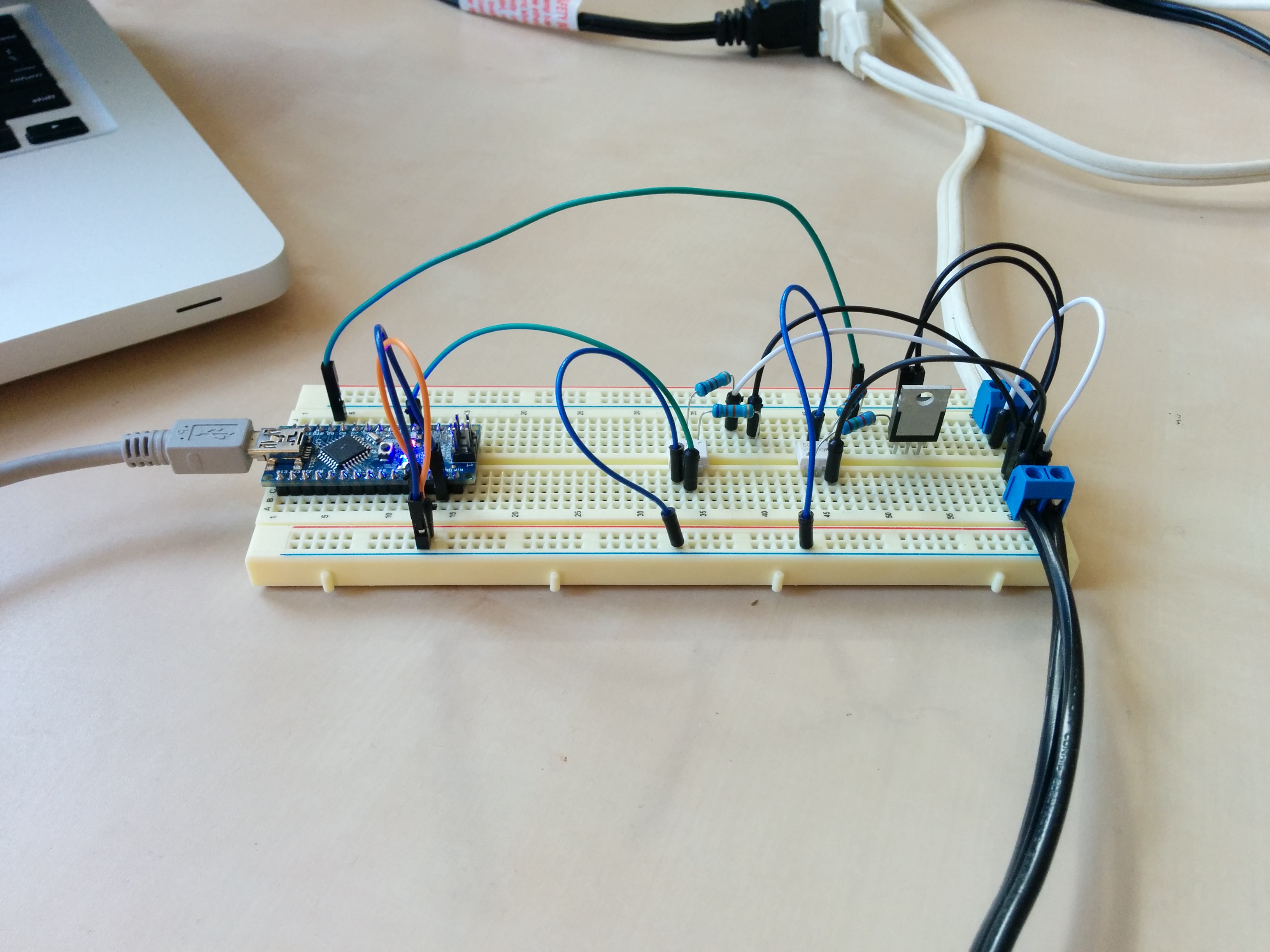
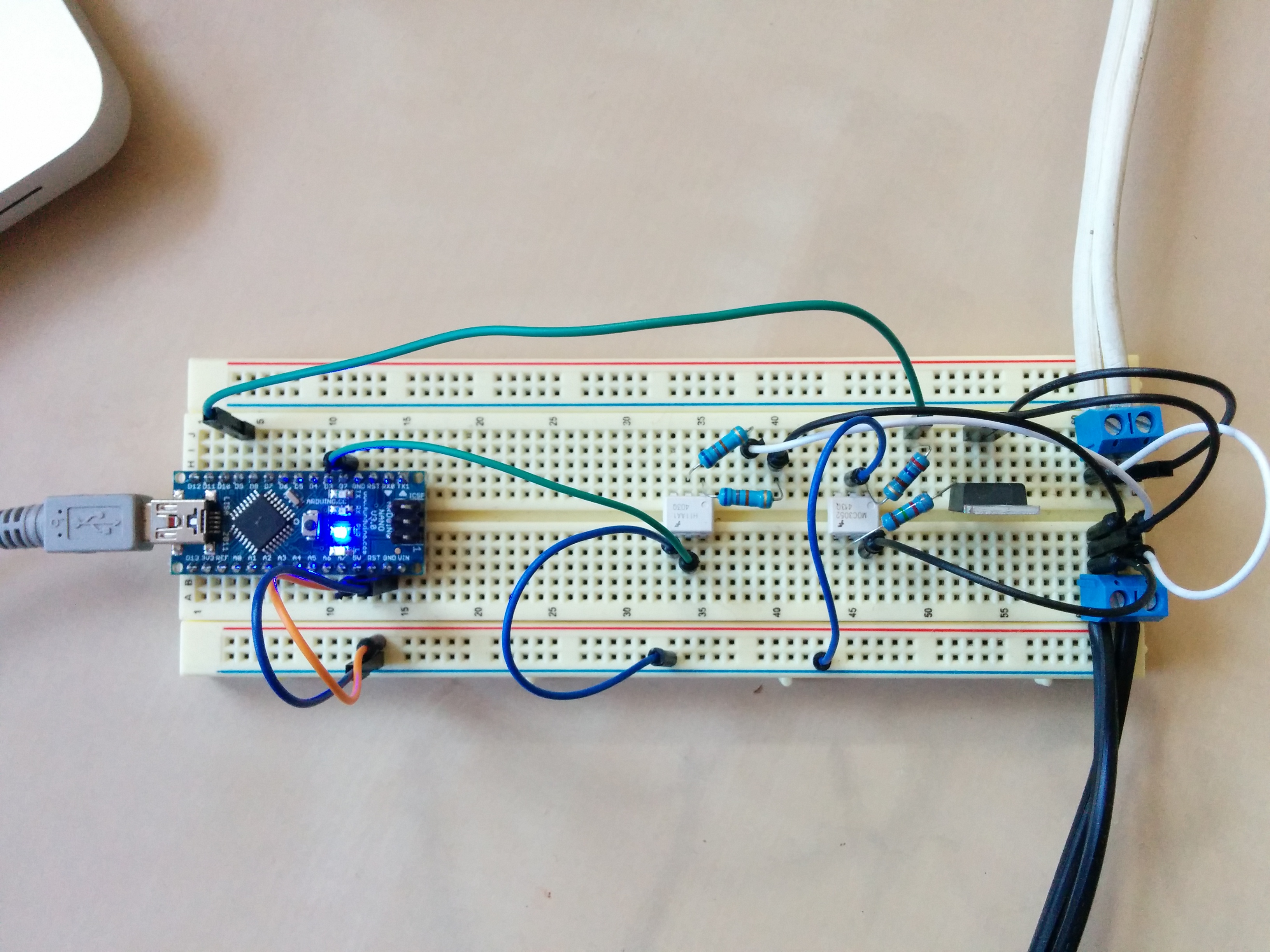
So I had been playing around with AC phase control to create things like software controlled light dimmers. After I had that under my belt I built this prototype to test controlling it based on an audio signal. It demonstrates a simple audio visualizer device utilizing any lamp I plug into it.
Since this is just a quick prototype, and I was just driving one desk lamp, I took some temporary shortcuts. If and when I do anything further with this I’ll make it more robust by soldering everything up on perf board or a custom PCB, and using proper gauge wire, and clearances. There is a fuse in this circuit, built into the plug going to my wall outlet.
Here’s the schematic:
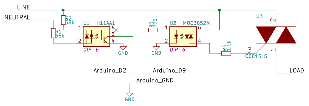
The flow of AC is being controlled by a Q6015L5 TRIAC which can handle a large enough current and the stress of being pulsed this way. It is driven by a MOC3052 optocoupler TRIAC driver allowing a small DC current to control AC current. The microcontroller(an Arduino in this case) gets the AC timing(specifically the moment of zero-crossing) from a H11AA1 optocoupler which can be driven from AC to provide a DC current. I have a pin on the microcontroller for zero-crossing detection pulled high with an internal pull-up resistor. While the AC is not zero-crossing, the H11AA1 is being driven which pulls that pin low. At zero-crossing the transistor in the H11AA1 is off, and the detection pin goes high again. Zero-crossing detection allows for phase cutting which is essentially a method of doing PWM with an AC voltage. In this way the microcontroller can behave as a programmable light dimmer.
The microcontroller receives the target light brightness from my laptop over USB. This target light brightness is calculated in an app written in Processing which is playing and analyzing the audio.

For heck I tried this same AC phase cutting on incandescent tree lights and it worked pretty well too. Here’s the video of that.
