
A while back I was acquainted with the idea of using a capacitor to create a very simple power supply. A cap dropper circuit is a type of transformerless power supply, converting AC mains input to a much lower voltage output for low power components without the cost and bulk of a transformer. This is pretty cool since they’re really small and quick circuits to build. I built 2 versions to test some ideas out. Below is a video showing them working, some circuit measurements, and some explanation.
CAUTION:
You should not attempt to build, test, or use this type of circuit unless you are experienced and competent in handling AC mains and high voltage. Do not touch this circuit. Depending on how it’s built either many or all points are at mains potential while powered. Further any point in the circuit can be at mains or higher voltage at any time, all it takes is a single component failing or some spike on mains. There is no transformer or other source of galvanic isolation. Even after disconnecting from mains, the dropping capacitor can hold a dangerous high voltage.
WARNING:
A low voltage between two points in a circuit, DOES NOT mean that there is not a high voltage between one of those points and earth ground(you). The AC voltage across an LED may be a few volts while the AC voltage between either leg of that same LED and you could be dangerously high.
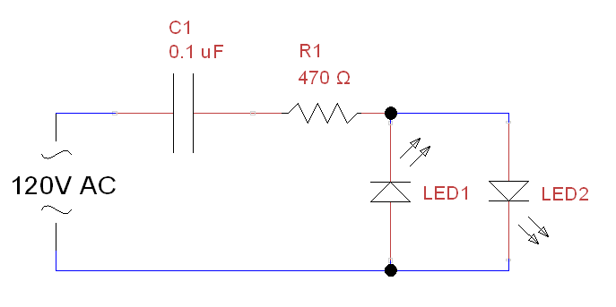
The first circuit, very minimal, powers standard red LEDs from mains. It’s one thing to read theory about impedance from capacitive reactance, but another to see it really playing out in a circuit you’ve built. The 100 nanofarad capacitor provides about 26 kilo-ohms of impedance, which can be calculated with Z = 1/Cs = 1/(100(nanofarads) * 10^-9 * 60(Hz) * 2 * PI) = 26,525. This drops enough voltage and limits current through the LEDs to an amount well within their rating of about 2V @ 20mA. As a quick starting point for determining the impedance required(which in turn specifies the capacitance value): First, choose the current you want going through the LEDs. Then divide your expected voltage(less the LED voltage drop) by the current you want. As a rough estimation example:
(170V{peak} – 2V{LEDs})/0.006{6 milliamps} = 28K
Note:
Many things would make this circuit somewhat safer and more robust, including using an X-rated capacitor(example pictured at the bottom) and a proper fuse. Also, even in this case where I’m just using a common capacitor I got from RadioShack, it must be non-polarized since the mains AC will reverse polarity of the voltage every half cycle. So polarized electrolytics are out. Also it must be rated at least for the peak voltage(not just the stated RMS voltage), which excluding spikes will be 120 Vrms * sqrt(2) = 170 V in the US.
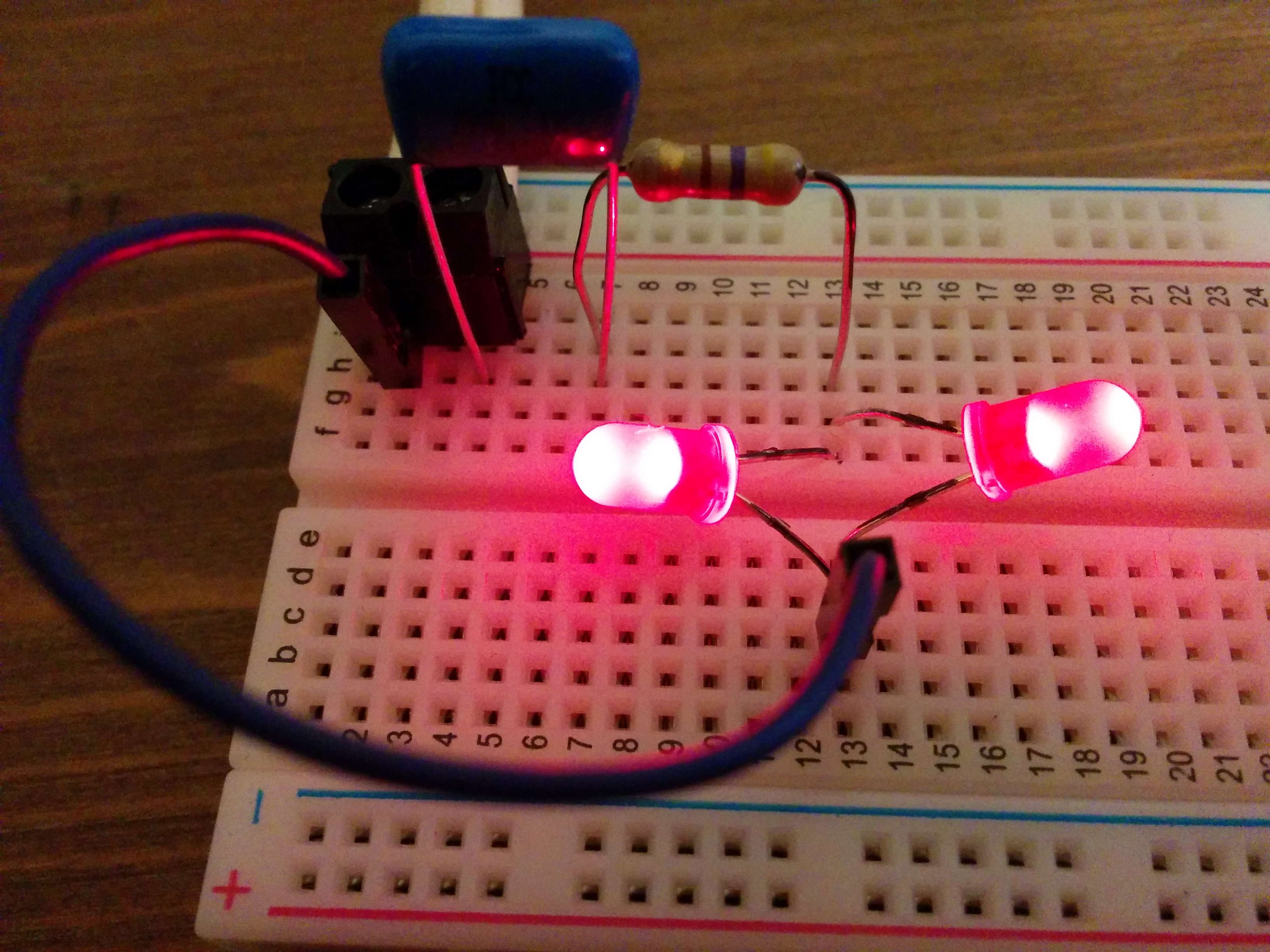
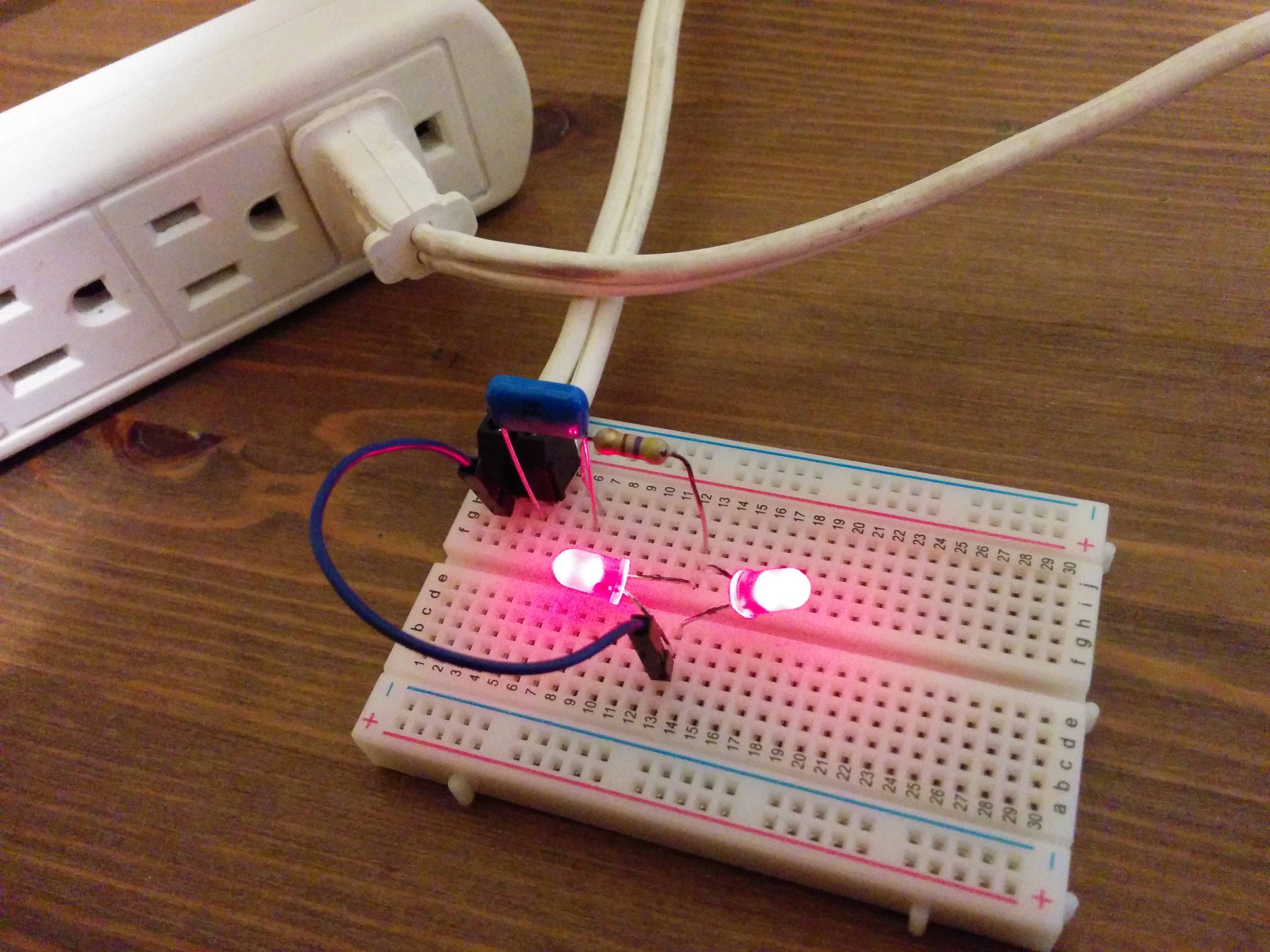
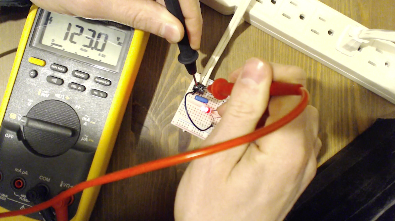
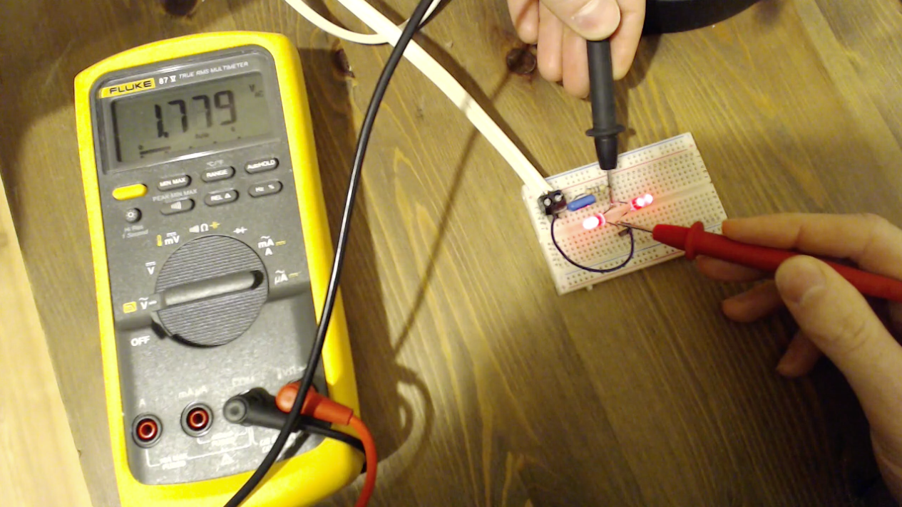
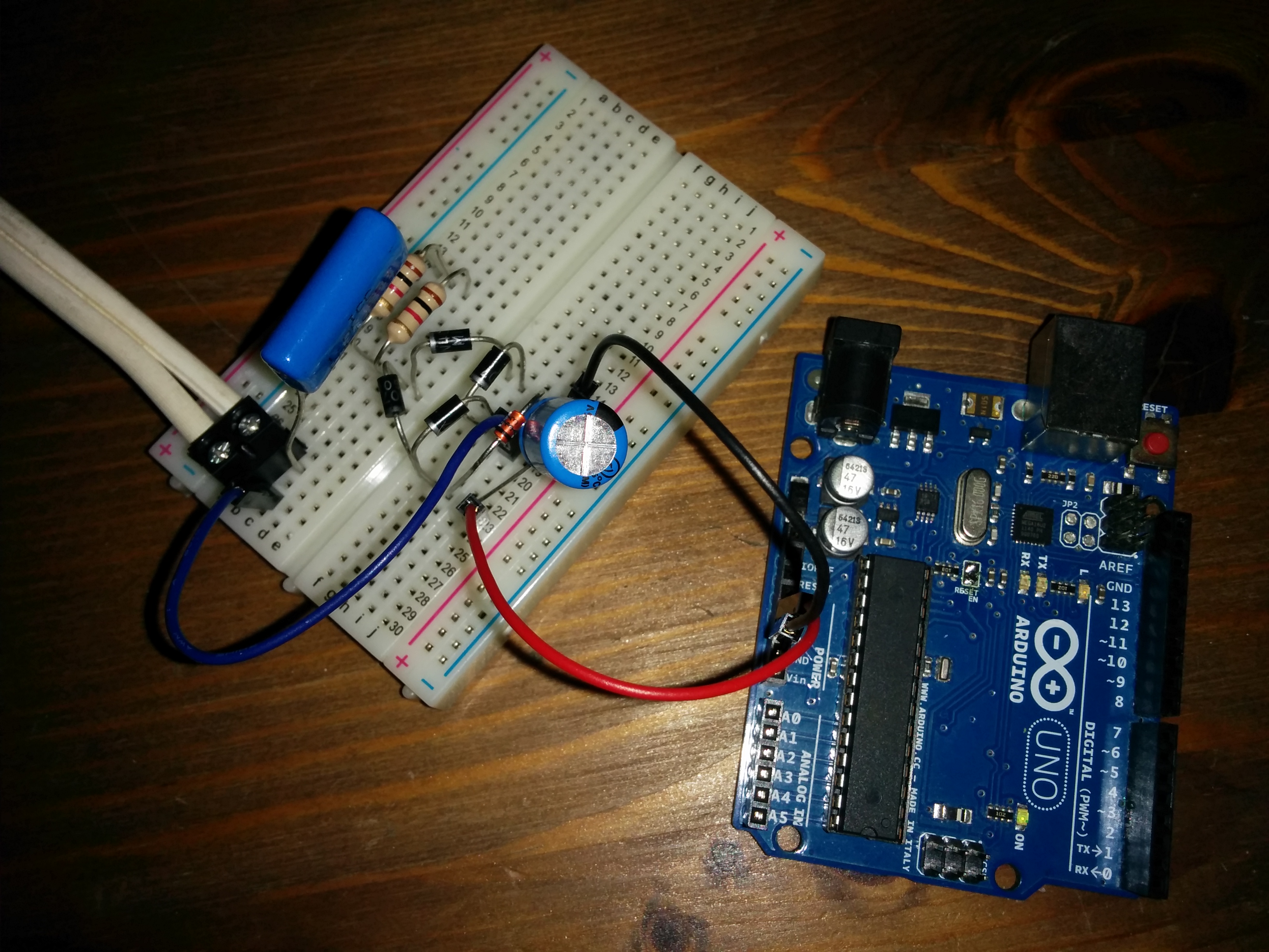
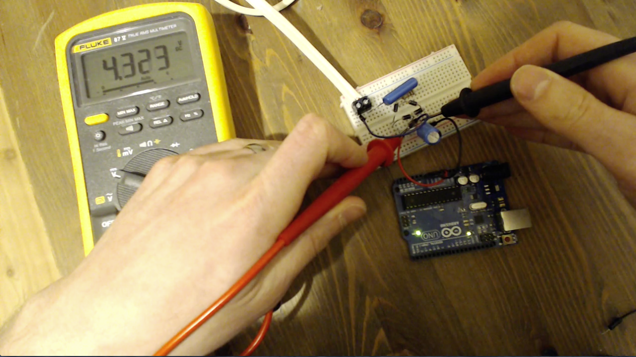
The second circuit is outputting almost 5V DC for running an Arduino. Like cap droppers in general it is not designed to source much current. Even the Arduino is pulling enough to cause the voltage to drop a bit below 5V. There are many variations on a circuit like this. This one is rectifying the remaining AC voltage that isn’t dropped by the input capacitor. The rectified DC is capped by a 5.1V zener diode and buffered in the output capacitor to smooth it out a bit.
WARNING:
Even though there is only 5V or less between points on the Arduino, does not mean there is not a dangerous voltage between a point on the Arduino and you. Arduino ground, especially in this case, is not the same as earth ground.
Similar to the first circuit, a resistor is used to limit inrush current when AC power is first applied(in the theoretical extreme, an instantaneous change in capacitor voltage would necessitate an infinite current into the capacitor). Also the resistor somewhat limits the effect of a transient voltage spike. Without these, in the first circuit for example, the LEDs will burn out after turning the power on and off a few times. The reason for 2 in the second circuit is higher current involved and I didn’t have a proper wattage resistor so I put 2 in parallel to achieve the same thing, to avoid the resistor overheating. The resistors do somewhat limit the current but in these circuits the capacitor’s reactance is doing most of the work, and dropping most of the voltage.


Hello. I am having trouble understanding your second circuit. With 1 uF it works out to about 2.61k for the resistor.
I am also having trouble understanding the value you chose for the R1. I am making an LED strip to run off of 120VAC. 2.5V ina series of 10. I am shooting for 24 volts and the LEDs are rated for 70 mA.
Hi Timothy. R1 is used to limit inrush current and the effect of other transients. But more importantly, this project is just to demo some interesting electronics concepts and does not in any way show safe or proper design as presented. It was done for educational purposes only. To run an LED strip off of mains you should definitely buy an off-the-shelf LED driver. This will be much safer, more reliable, and should be quite affordable. There are models that set a specific voltage or a specific current as required.
Ahh…. About the formula.. I think I understand it pretty well at this point, but I was wondering where the number two in the formula has come from. Is that just a standard part of the formula or is that the voltage of the LED? I don’t really see how it would be the LED, but I just wanted to make sure. LOL
It’s the leds characteristic voltage.
Each colour has a different one, and it does depend somewhat on the current through it, and those voltages are here
Red 1.8 V to 2.1 V
Orange 2.2 V
Yellow 2.4 V
Green 2.6 V
Blue 3.0 V to 3.5 V
White 3.0 V to 3.5 V
Ultraviolet 3.5 V
So you can see why Bob took 2 as a nominal value. I usually neglect subtracting the LED voltages, as it makes less than 2% difference to the calculations, less for places where the supply is 240Volts. Capacitors have typically 10 to 20% tolerance, so the led voltage is small beer. I believe Bob is showing principles, and for that, accounting for the led voltage is proper.
Hi Bob,
Nice explanation for this kind of circuit. However two points:
Why an X2 rated dropper cap? X type caps are primarily intended for line to line use and designed to fail short circuit. When they are used in their usual application – as line filters – the idea is that they trip a breaker or fuse, so protecting life, limb and appliance.
When used as the main dropper in a cap-drop power supply however, going short means they will take out the rest of the circuit.
Generally the kinds of electronic circuits powered by a CDPS (Capacitor Drop Power Supply) blow so quickly that any mains fuse or even a miniature fuse often does not have a chance to blow. That usually leaves parts of the circuit live. In “typical” use the devices the capacitors are filtering are usually motors or something similar that can withstand the peak currents associated with a brief short. Besides, the load is in parallel to the capacitor, not in series as with a CDPS, so a shorted cap has no effect on the load itself
The generally higher impedances of the load for a CDPS can mean a normal mains fuse will never see sufficiently high current for long enough to blow should the cap fail. But there is certainly enough current and voltage to blow open any electronics in the path.
In other words, failure in an X rated cap used in series will (always?) take out the circuit it was supplying.
I have always considered Y rated capacitors to be a better solution, as these are intended to fail open circuit, which leaves the electronics more likely undamaged, and the mains voltage isolated (provided the cap was in the active leg) which of course cannot be assumed.
In reality though, I don’t always practice what I preach. I usually use an X rated cap because they are cheaper, or two caps in series, each double the effective needed values, and each capable of handling the full peak mains voltage plus safety allowances. But it all depends on the space available, the cost of writing off the entire circuit if there should be a failure, and the fire containment issues.
For a CDPS powering a few leds it’s cheaper to write the whole thing off, and accept the leds have become the fuses. For one powering a microprocessor, maybe take some better precautions against power supply failure.
The other point of interest are the calculated values for both the bleed resistor and the peak current limiting resistors. The resistance values are just as you show, but If the resistors are specified based on power dissipation you nearly always wind up with something in the less-than-quarter-watt region. The problem here is that .25W resistors are tiny, and the failure mode these physically tiny resistors invite is internal arcing as the volts per metre rating is exceeded, leading to progressive and rapid failure, blackening, smoke, fire, shorts and tears.
To mask the inherent problem, the series resistor only experiences peak mains voltage across it as a turn-on transient, and then only if actual switch-on happens at a peak. So it usually takes many cycles of turn on and turn off to elicit a failure.
The bleed resistor is a bit more unfortunate, as it has mains AC voltage across it at all times. Without going into internal resistor construction, imagine a 1/8 watt resistor, of umpty megohms value, with 1000 VAC across it! The power dissipation may well be way below its 1/8W rating, so it calculates as OK to use, but would you trust a thing made of plastic, ceramic and metal and maybe only 3mm long to not break down with 1KV x 1.414 across it?
Here it’s the peak breakdown voltage rating that is relevant: nothing to do with its dissipation rating, and that rating is often not specified.
This is why you guys in the USA have it easy, and why you may not see the problems of resistor failure that I have: you are on a 120VAC grid, so the break over issues I am discussing are lessened. The rest of the world has to live with 220, 230 and here in Australia we “enjoy” a 240VAC house voltage (and 415V for 3 phase). That really sorts the men from the fried bananas. For these countries and voltages break over / flash over is much more a concern.
Where space permits, I recommend halving the calculated resistor value, using two in series, and making them 1 Watt, again where space permits. The higher wattage rating simply means bigger physical size and lower volts per length stress. Often just a single 1 watter is OK too.
Often CDPS are used for nothing more than powering a LED or two. I like your base design of two leds in inverse parallel. I have seen some designs with all manner of components at the front and, culminating in a diode bridge, a filter cap, a zener diode, a series resistor for the zener, more filtering then the load!!
If it’s LEDs one is powering, just connect the led (or series led string) directly across the DC output of the bridge. . No resistors needed in series with the LEDS, because it’s a constant current source supply.
Other viable configurations are:
diode bridge made entirely of LEDS, and DC output shorted. Gives 4 led brightness for the same current as one led
diode bridge made entirely of LEDS, and DC output loaded with another one or two LEDS (but no more). Gives 5 or 6 leds worth of brightness again with the same current draw as if only one led was being powered. The led(s) across the output will be twice as bright as the leds making up the bridge.
The thing to remember is that the maximum reverse voltage any diode in the bridge sees is 2 led drops, or 4 volts. Again, stressing that the output is clamped by a led or two as the load.
Other thoughts?