
In past CRT projects I still utilized the display’s CRT driver logic to do the normal beam deflection in a standard row by row raster pattern. But some devices such as old oscilloscopes by design steer the beam directly to what should be rendered. The path traced by the beam on the screen in this case is the curve of the lines being shown.
I wanted to try setting up a basic circuit to control the CRT’s electron beam deflection. Then I wanted to see what I could do with a microcontroller driving that circuit. Here’s where I got:
The CRT has 2 deflection coils, one for horizontal and one for vertical, to aim the beam. The amount of deflection is linearly related to how much current you run through the coil, with more current causing more deflection. You can run current in the opposite direction to deflect the beam the opposite way. For this tube, the useful range was on the order of 0.5 amps in either direction.
I initially tried having a target voltage on the coils to get a target position, but what you really need is a target current. Since these are by design coils, their inductance really comes into play and you can’t simply use Ohm’s Law to estimate a voltage necessary to get a given current. The amount of current already flowing through the coil (and associated magnetic field) largely factor into what voltage is necessary to change the amount of current to some target within a given period of time.
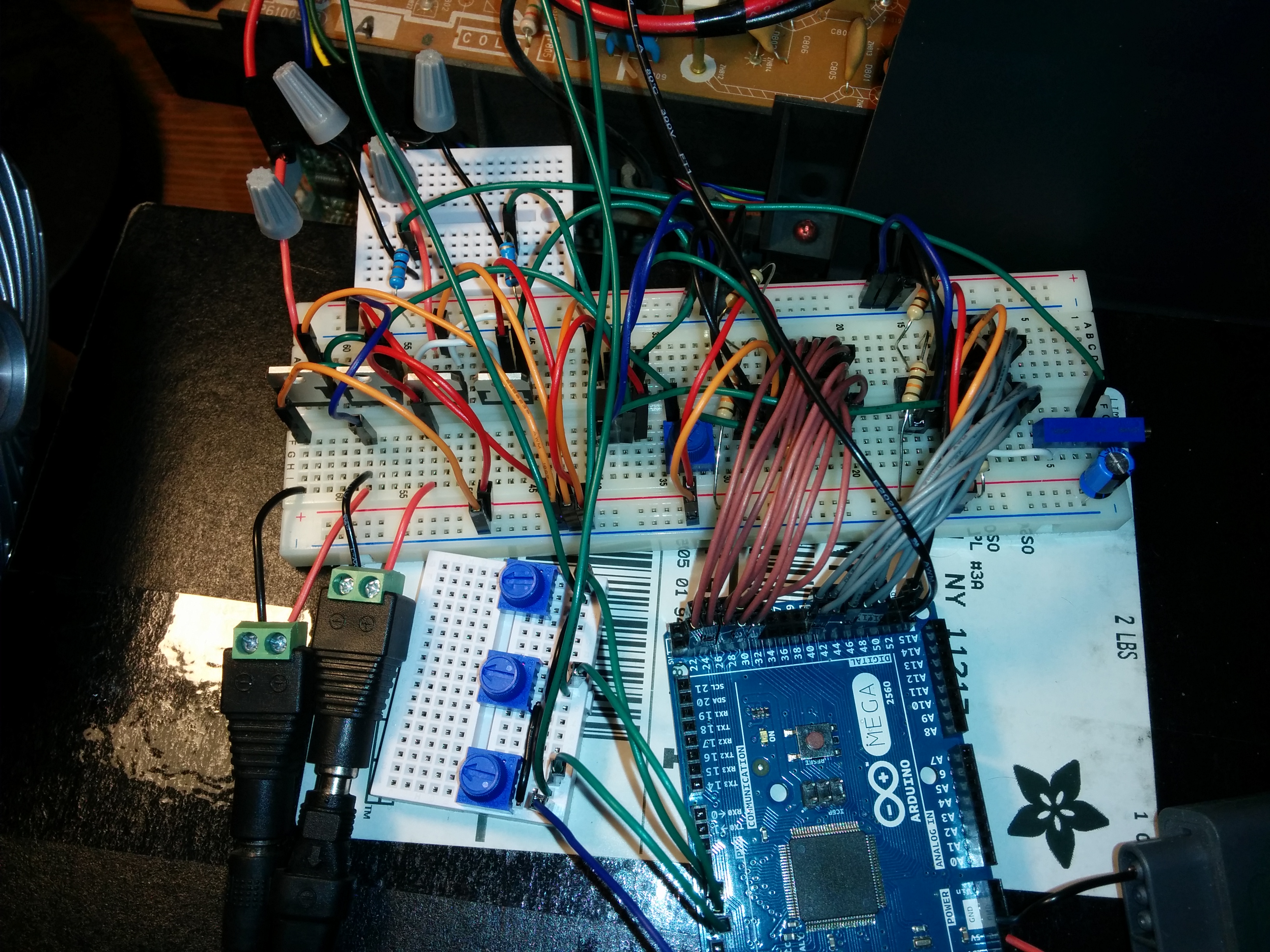
So I ended up using a 1 ohm resistor in series with each coil as a shunt resistor to measure the current running through the coil at that moment. The voltage dropped across that resistor linearly relates to the current. That voltage I could use as a feedback to the rest of my coil driver circuit.
For each coil I use 1 MDAC to set a reference for an op amp. The op amp drives the bases of a pair of transistors that act as a push-pull output which has more current drive capability than the op amp alone. The output current goes through a shunt resistor to ground on the way back from the coil. The voltage off this shunt I use as a feedback to that op amp. In this way the driver works as hard as it can to get the current where I need it to position the beam where I want. The rails for the op amps and push-pulls are +/- 9V. I have a pot set up with each MDAC to scale the reference voltage that it’s feeding the op amp I paired it with. These in effect tune the horizontal and vertical scaling.
Then there’s toggling the 3 color beams themselves. On the back of this CRT there’s a transistor for each beam. 5V from any of the mcu outputs is enough to turn these transistors full on, so the current version I have a pot for each color setup as a voltage divider between that output and ground to control the brightness of that channel.
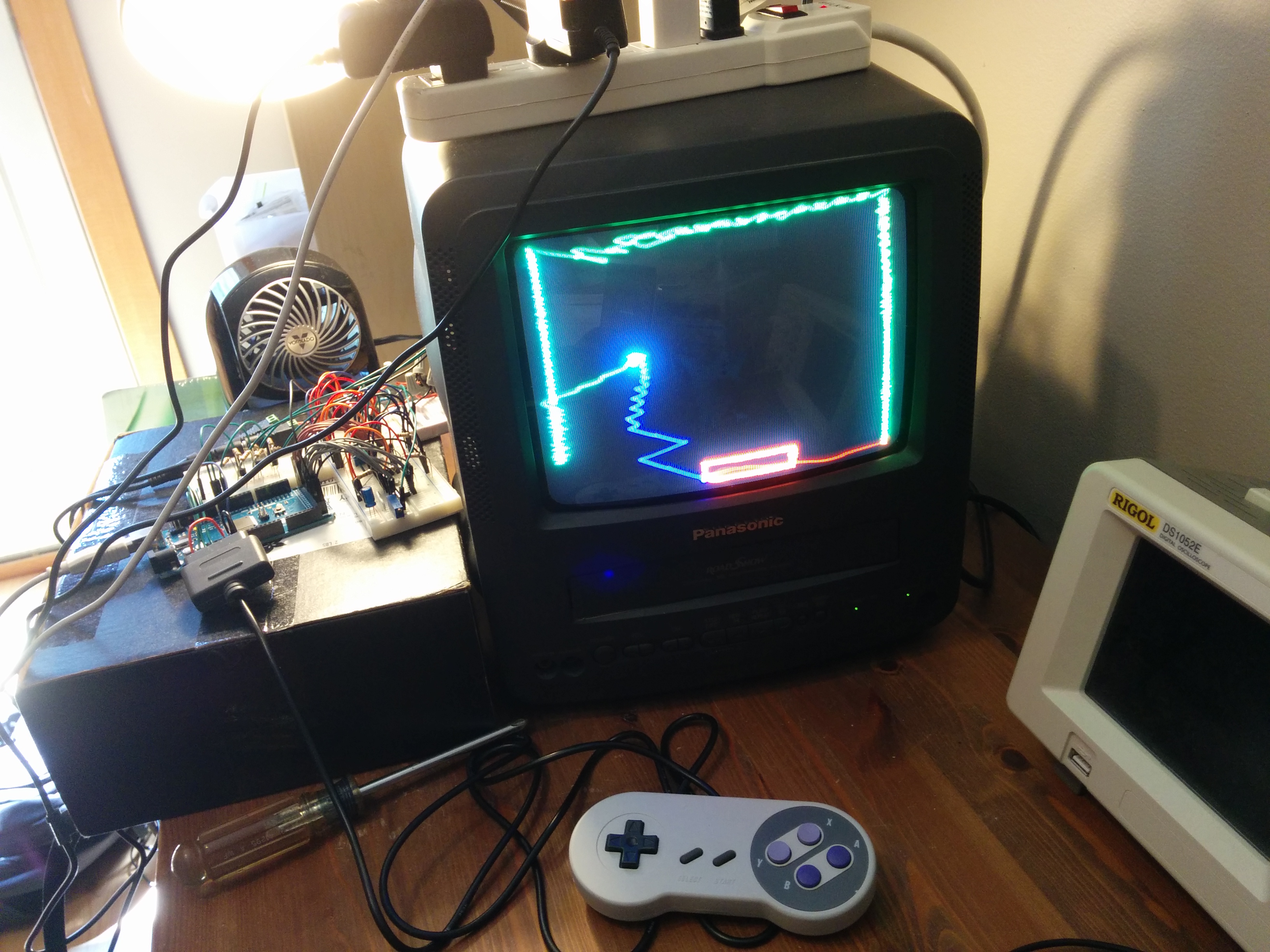
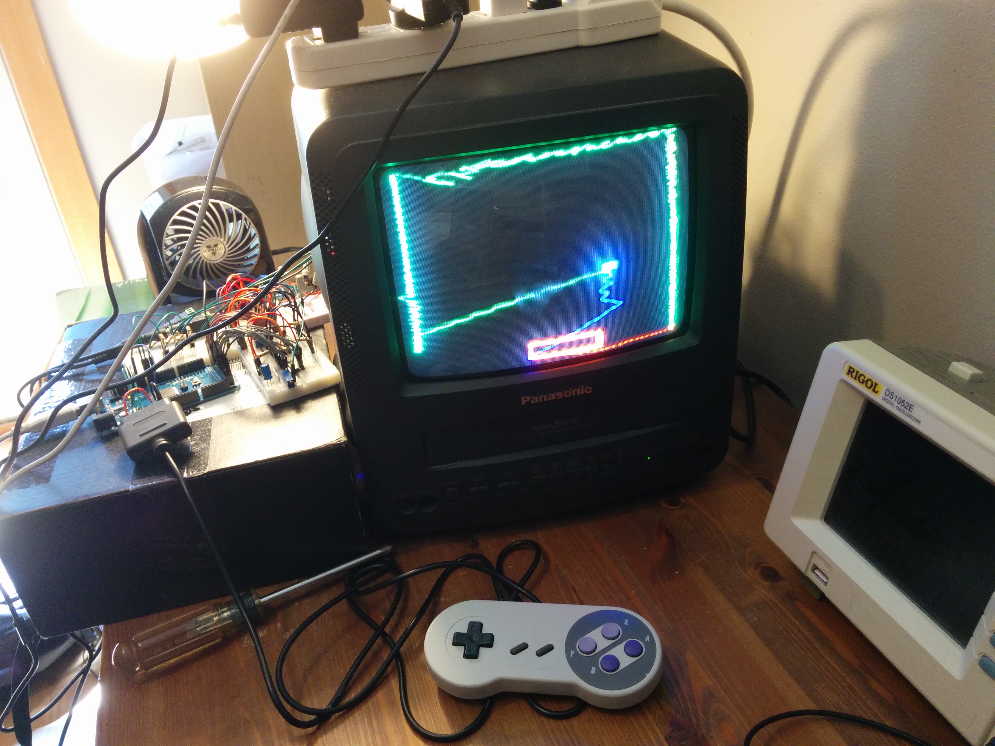
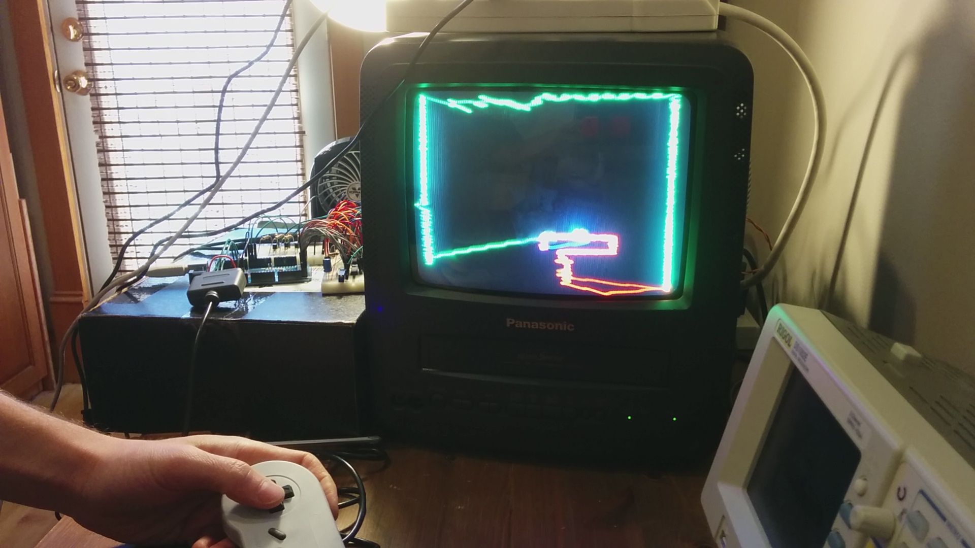
I initially had a test of just drawing a box on the screen. Then multiple boxes. Then multiple boxes moving. Then multiple boxes of different colors moving. Eventually I wanted to try something simple but interactive. I settled on a ball and paddle game. I was satisfied to take it to the point where I could move the paddle around, constrained to the screen, and have a ball that bounces off walls and the paddle. Add to that the ball’s ability to be ‘lost’, reset, and be launched and I felt pretty good about showing I could do a simple game with realtime interaction on this type of display with this 16 MHz, 8-bit mcu.
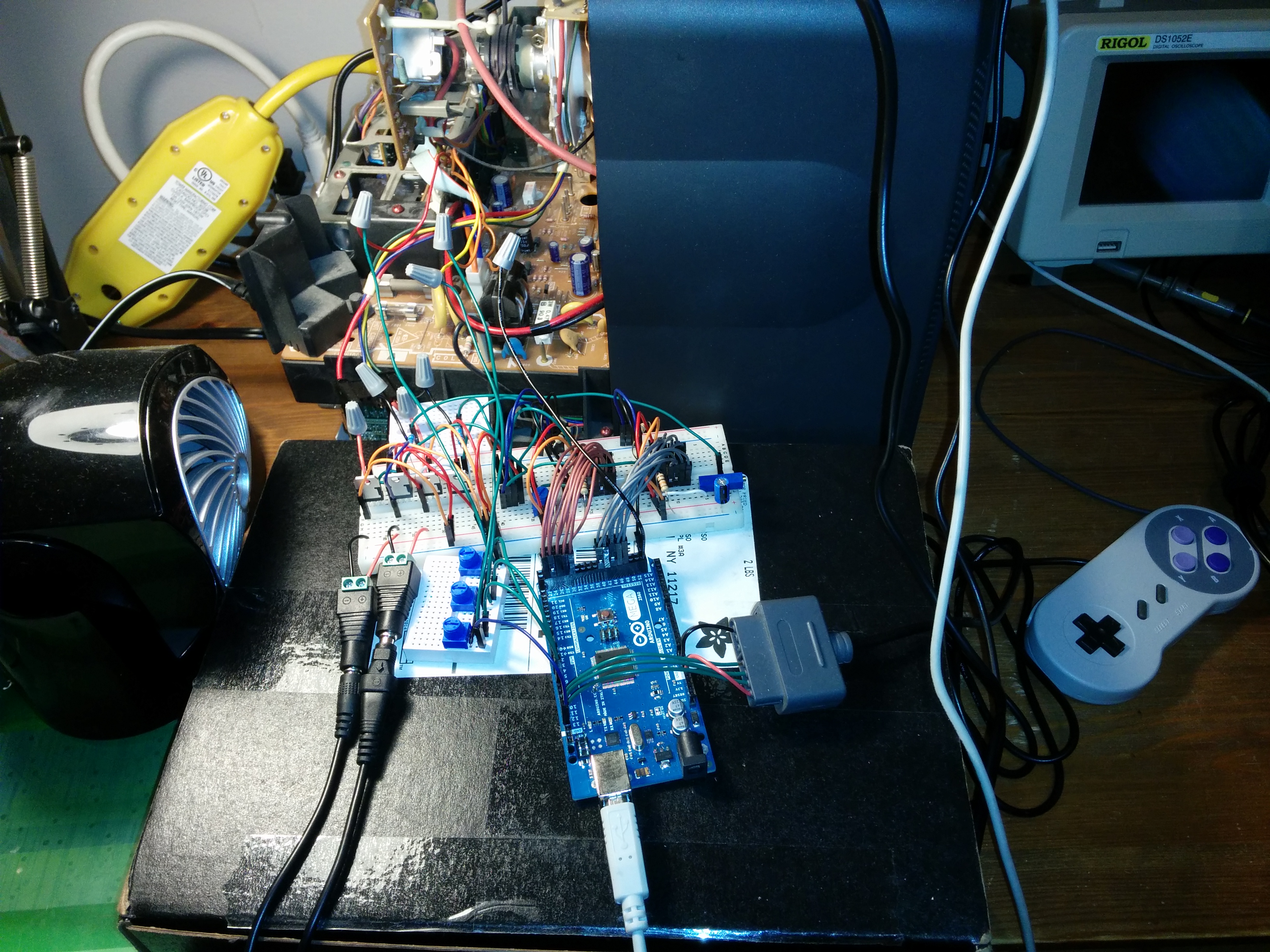
For the game’s controller I originally was going to use a simple 2-pot joystick, but, I had this 3rd party SNES controller laying around so after doing some online research it turned out to be pretty easy to wire up.
For a microcontroller for this project I had an Arduino Mega on hand so I decided to use that since it had a large number of GPIO pins broken out which was the main thing I needed. The 2 MDACs I chose were parallel input 10-bit, so the 2 of them were already 20 pins. Add to that 3 pins for the CRT beam colors and 3 pins for the SNES controller interface.
By the time I finished the game test, the week of my wife being away was wrapping up so I figured why not try an art project.


One thought on “CRT Electron Beam Deflection w/ Microcontroller”