
To switch adapt something means to make it more accessible for a person with a disability by setting it up so that adaptive switches can control it. These switches come in many different types to accommodate different methods of activating: pushing, pulling, pressing, sip-puff, eye-gaze, etc. Here’s a good write-up on switch adapting some toys:
http://www.diyability.org/projects/switch-adapting-a-remote-control-toy
In that example above, switch adapting involved making permanent modifications to the object. Sometimes you can get around that if desired. Let’s say for example you had a radio with an IR remote. You could create an alternate IR transmitter that was switch adapted quite easily. Using this alternate remote, the radio can be controlled with an adaptive switch without modifying either the original remote or the radio itself.
Another, adaptation that doesn’t require any permanent modifications is a battery interrupter. These can be purchased or even easily made yourself:
http://www.diyability.org/projects/make-a-battery-interrupt
http://www.instructables.com/id/No-Solder-Battery-Interrupter/
Sometimes however you have a device where neither of those methods is applicable. And sometimes, given the details around ownership or the financial risk, direct modifications are not an option. For those situations, one option can be a motorized button pusher. Then the button pusher is all that needs to be switch enabled.
Here’s a video of a button pusher I built and setup to control a hospital bed, in effect switch adapting the hospital bed indirectly:
Again, no modifications were made to the bed itself. All that was done was to attach the button pusher to the bed using screw holes that already existed. In other situations it could be clamped on easily instead. Or, if desired the button pusher and remote could rest on a table or other surface near the bed. For another bed I set up, zip ties worked well to mount the button pusher to the bed temporarily.
CAUTION:
This technique should not be used without additional safeties if there exists any manner of button pressing that could harm the user. In this example, if some of the bed’s positions could cause harm and if the controller failed or locked up, the user could end up in one of those positions and be injured. Although the example demonstrated here is controlling a hospital bed, this technique can be used in almost any case where you have an object that is already controllable with buttons. Safety and level of risk must always be considered for any equipment adaptation.
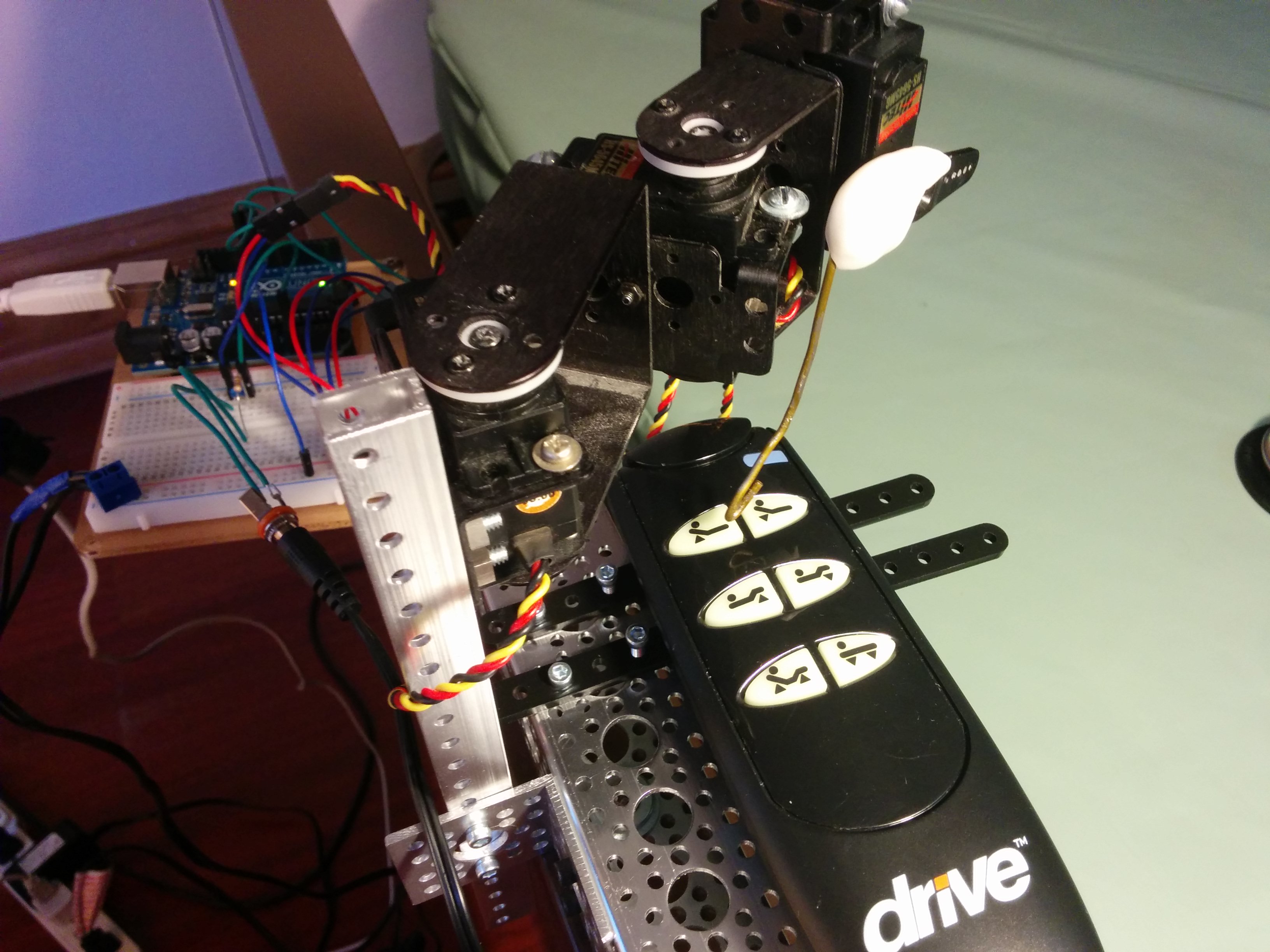
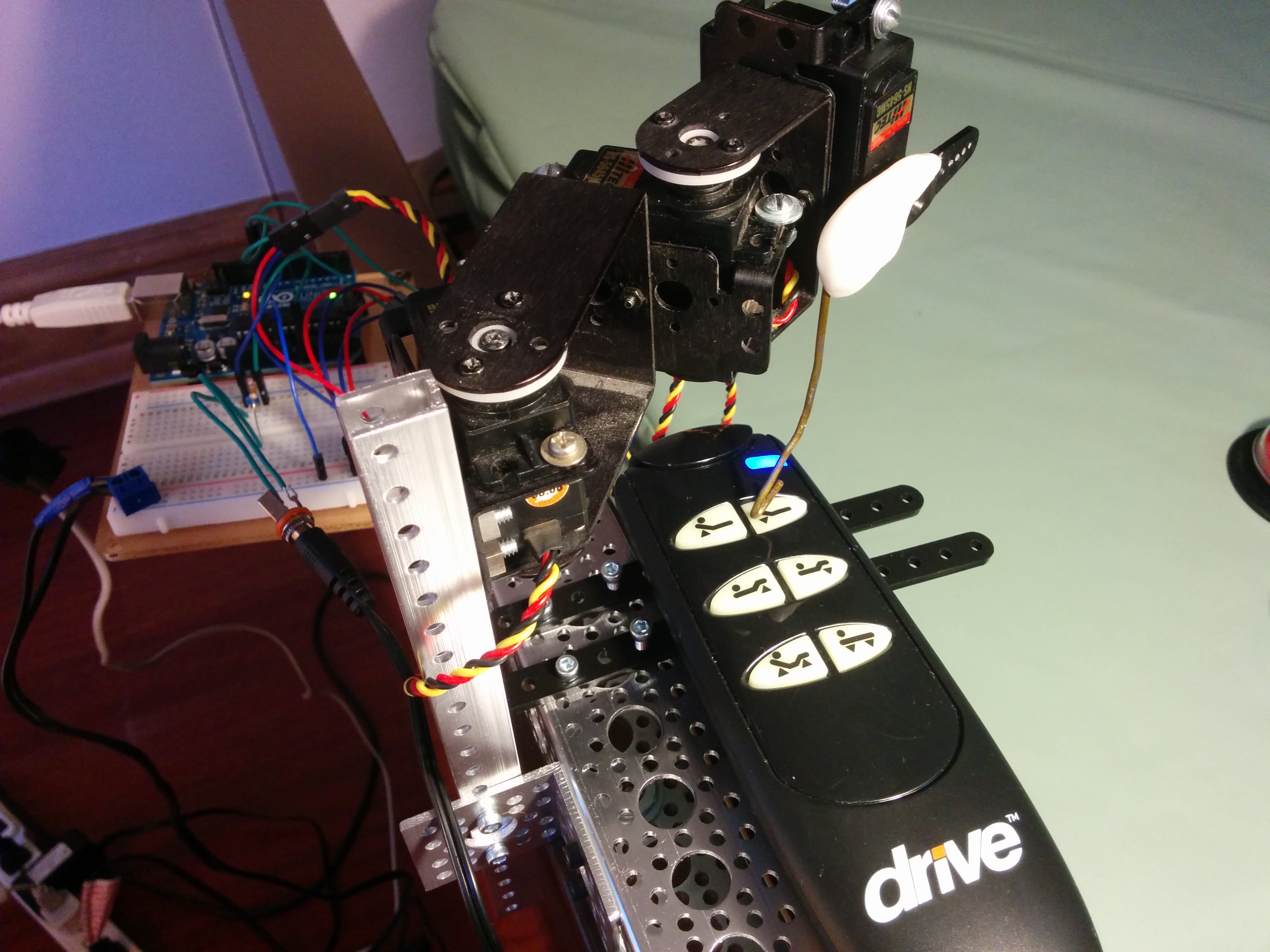
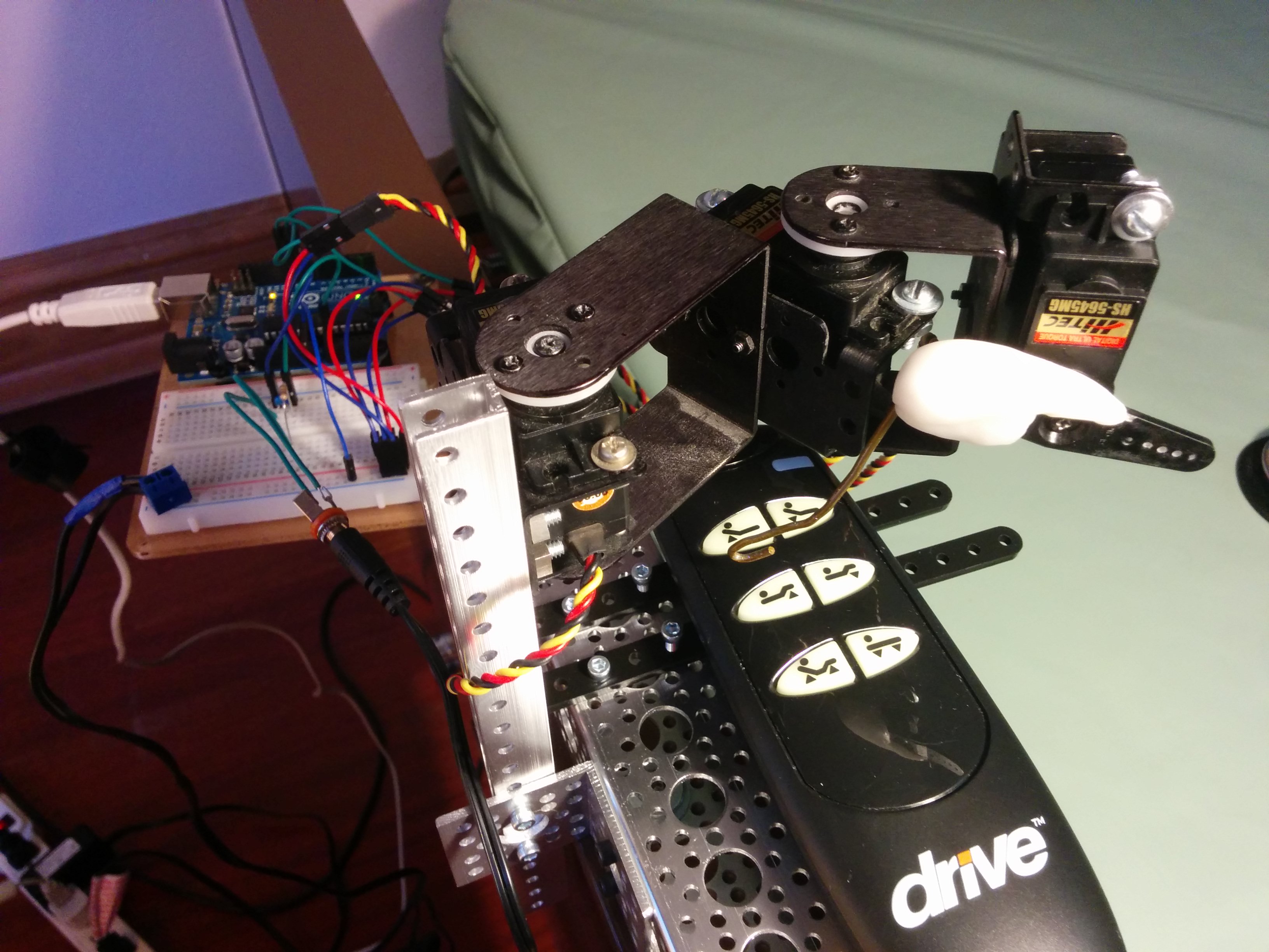
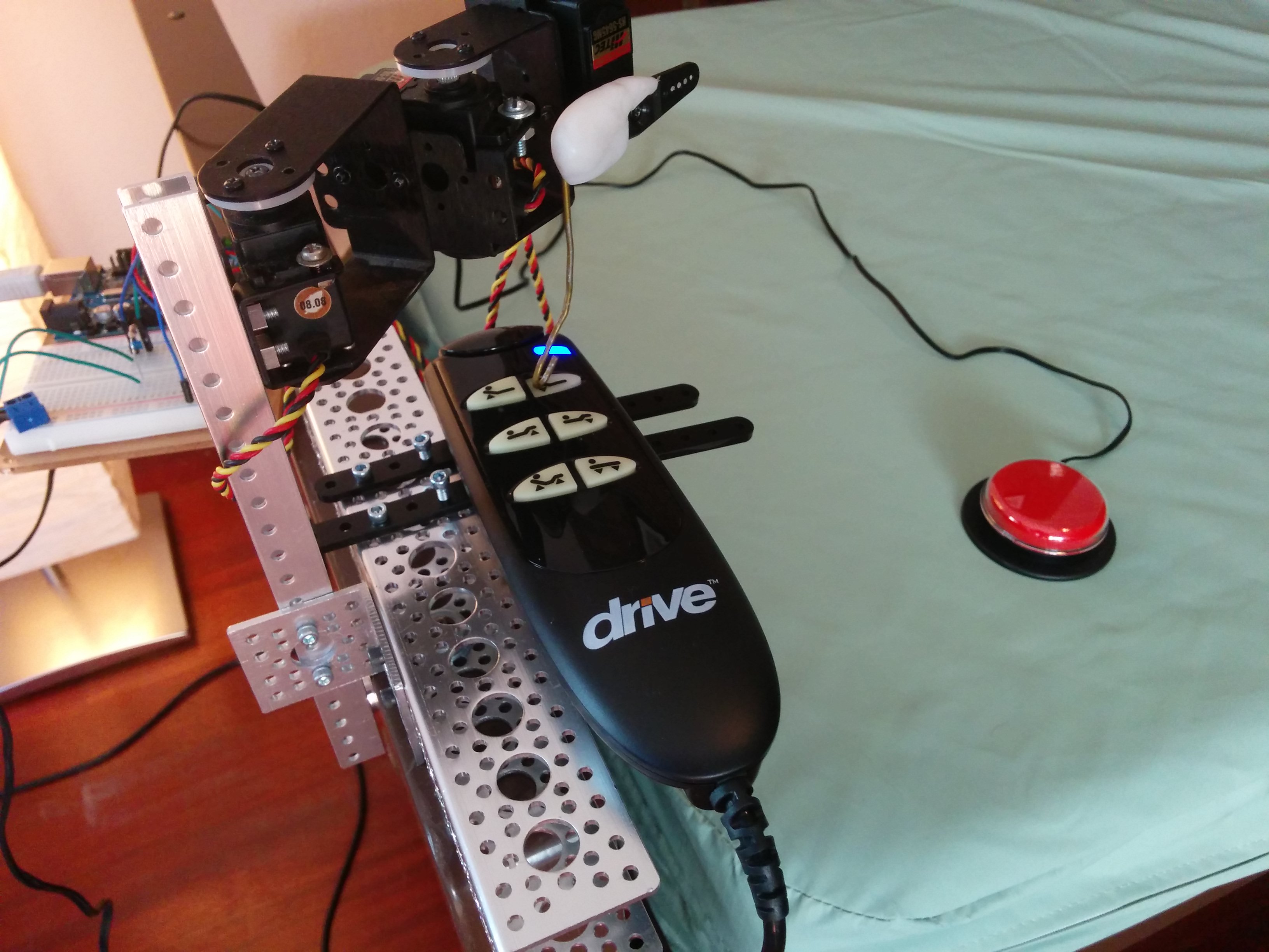
Here’s a closeup of the button pusher test hitting each button on the remote:
I designed, built and tested that first version on the first bed over the course of a day. Setting it up on a different bed and ‘teaching’ it where the buttons are on a different remote was much faster. Here’s that same button pusher and first bed being voice controlled with Amazon Echo:
Connecting the button pusher to Echo follows the same technique I used in this project:
https://bobparadiso.com/2015/07/17/amazon-echo-controlled-wheelchair/
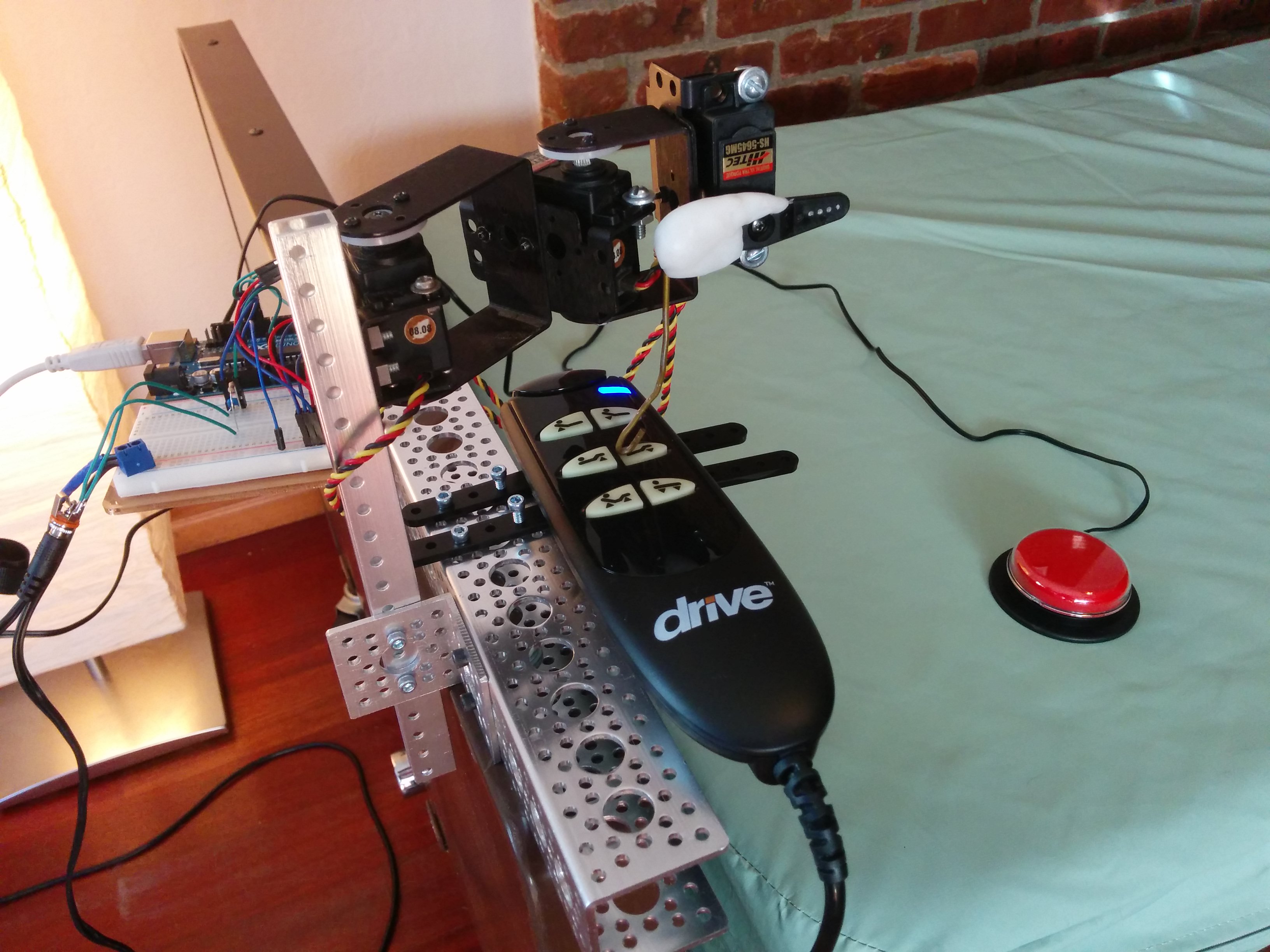
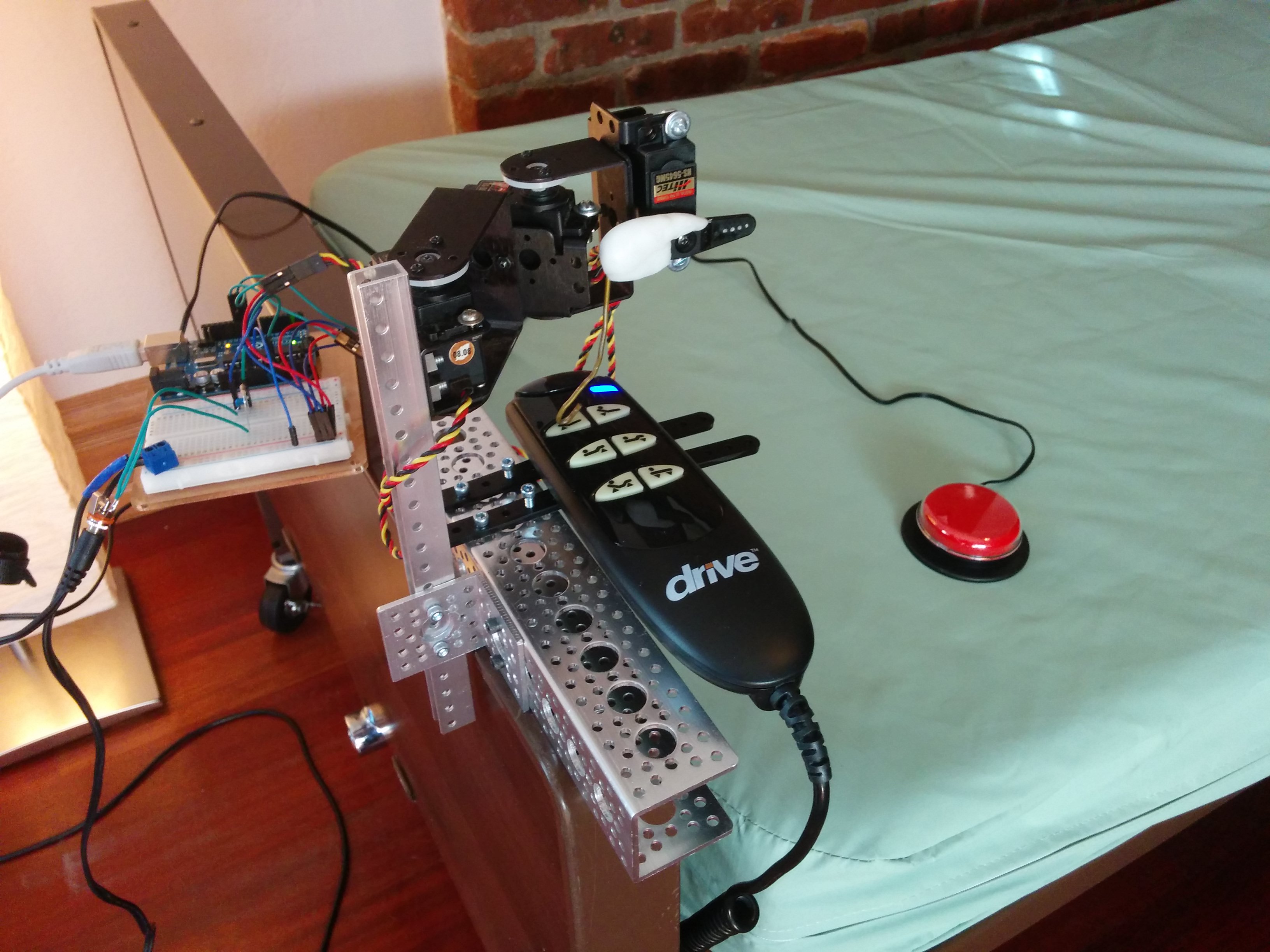
The mechanism uses three servos: 2 of them provide the XY position over the target button, the 3rd controls pressing down on that button. I had to iterate some on the mechanism, but I ended up with something that can work for a wide variety of button layouts. An Arduino is used to control the servos based on the adaptive switch, or voice commands via Amazon Echo.
The structural hardware came primarily from 2 places:
http://www.lynxmotion.com/
https://www.servocity.com/html/actobotics1.html
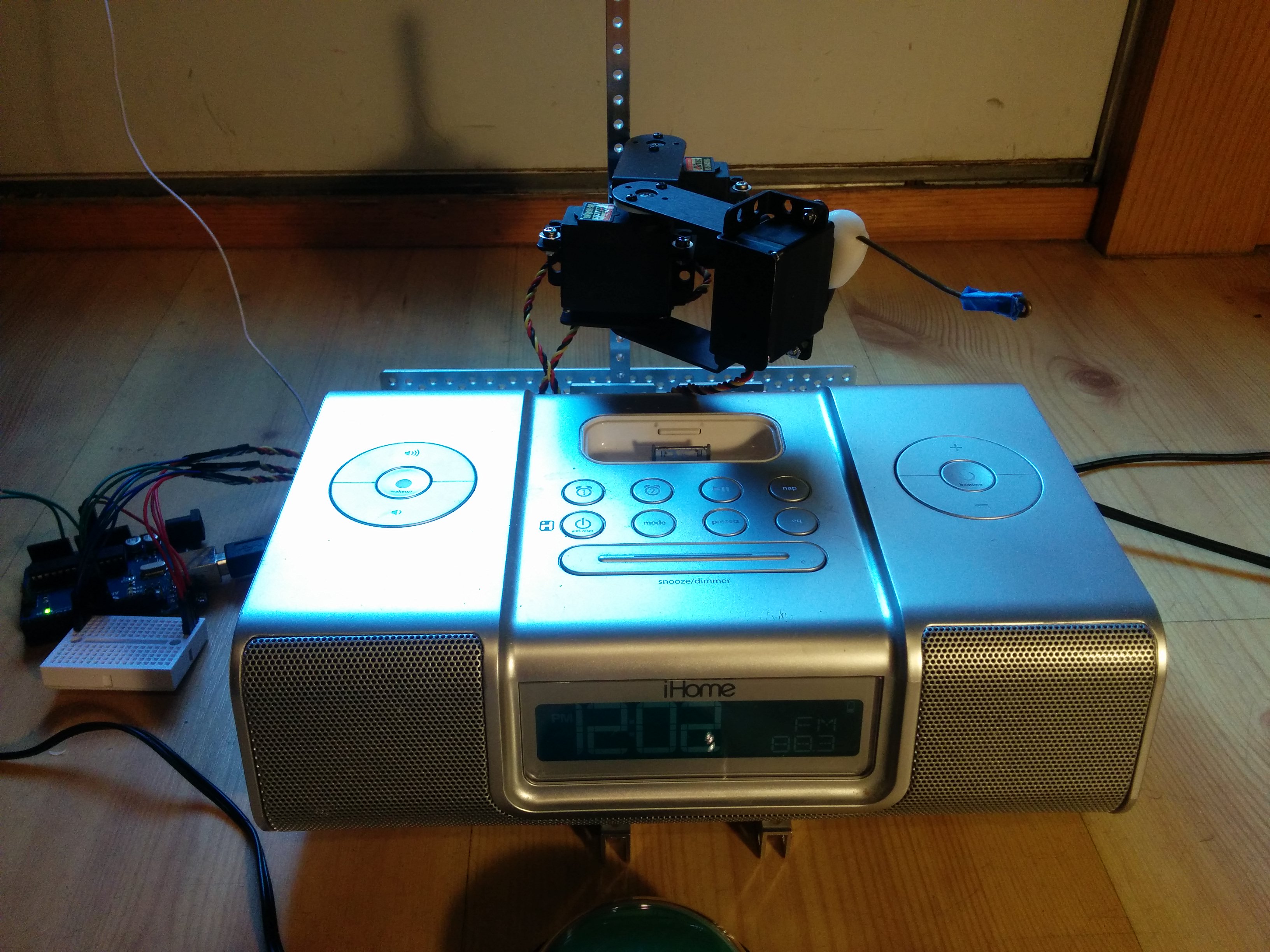
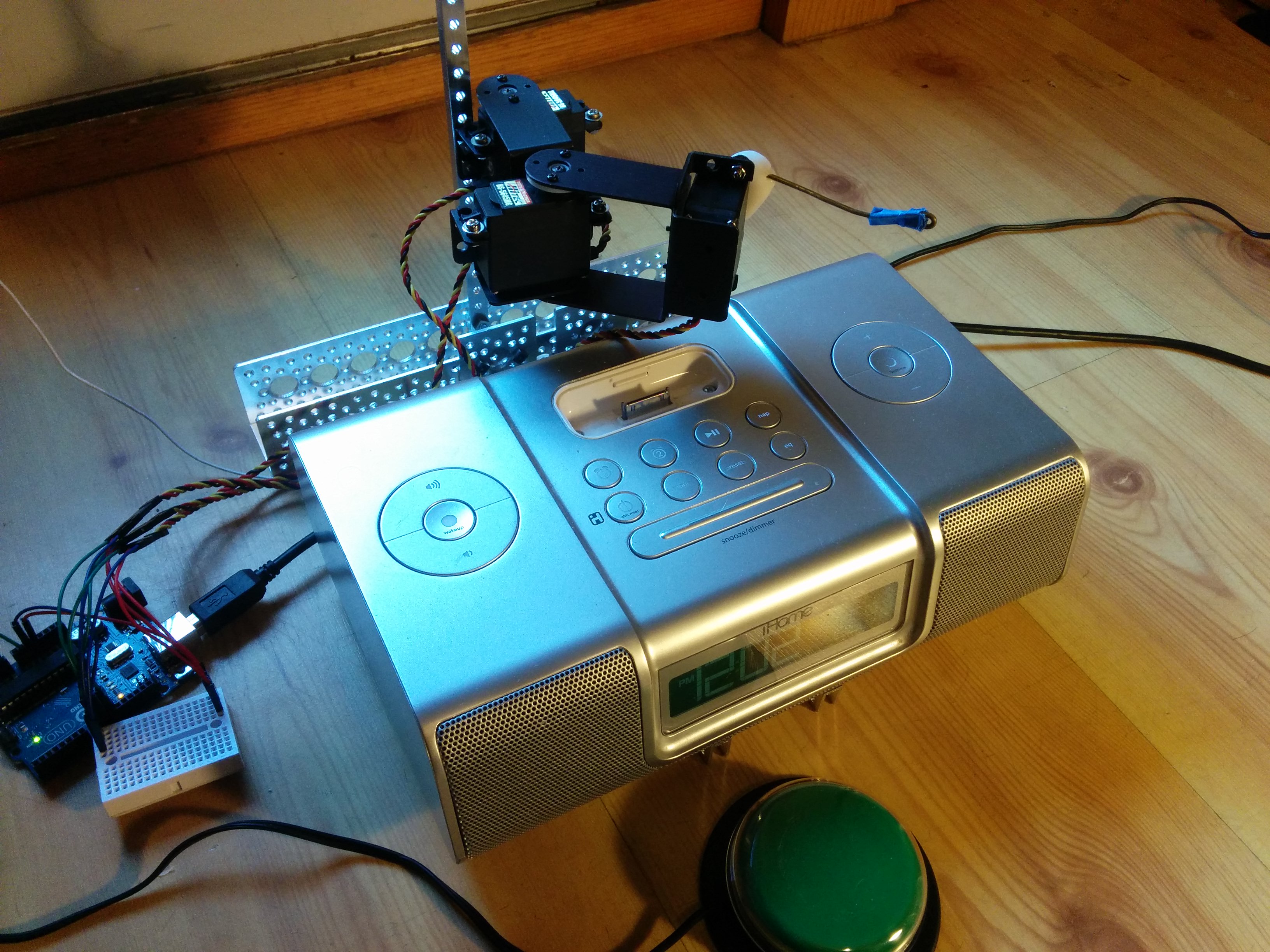
Here’s a different example, where the button pusher is being used on a radio:
CAUTION:
With any equipment modification, failure cases must be considered and their risk to the user understood. Given the bed example as-is, you MUST consider what would happen to the user if the button pusher locked up and continued pressing a button such that the bed went all the way to one of its extreme positions. You MUST also consider what would happen if the wrong button was pressed. If either of these could harm the user in any way, then this adaptation MUST NOT be used as-is without other safeties in place. Failure can be mechanical, or in software, or in the communication or connections between parts of the system. Individual parts must be tested and the system as a whole must be tested, rigorously, depending on the level of risk. That said, this technique is another way to further enable someone to control their environment.
On the other hand, in the case of controlling something like a radio or TV, there may be no risk at all.
Bed Demo Setup


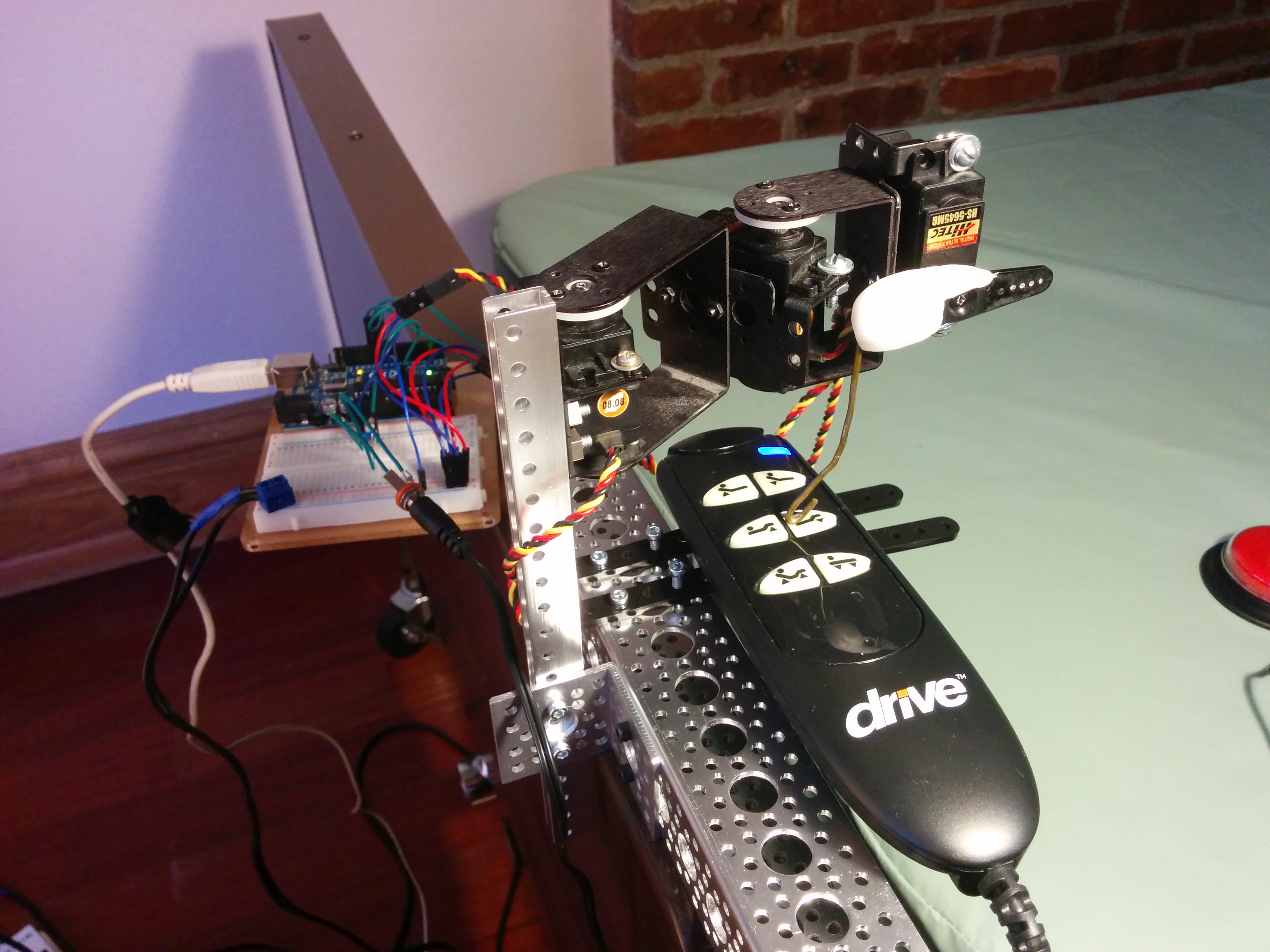


Radio Demo Setup
You can grab the code I used here:
https://github.com/bobparadiso/UniversalButtonPusher
The .ino file runs on an Arduino and controls the servos. The .pde file runs in Processing on your computer as a means to more easily calibrate the servo positions. Your computer and Processing are not used at all and are unnecessary in the normal usage of the button pusher.
You can also send commands to the Arduino over it’s USB port to control the servos or calibrate them.
Command set:
s 0 1500 //set servo 0 to position 1500
b 2 1000 //press button 2 for 1000 milliseconds
p 1400 //momentarily press ‘finger’ servo to position 1400, other servos hold current position

will you please share wiring drawing… or is just want to know about, #define SWITCH_PIN A0
how it is connected, on analog pin or digital, because ”int switchState = digitalRead(SWITCH_PIN);” here it is looking a digital input
Thank you for your comments sandeep. The analog pins on this microcontroller can be used as analog or digital. In this case I’m using A0 as digital, and have chosen it for it’s physical location on the opposite side of the board.
i must say very great work u did hats off
Looks really nice. Can you tell me which servo motor you used?
I am planning to do something like that to integrate my Bose Soundlink 3 Speaker into my Smart Home. I already tried to use solenoids for button pressing but they were not powerful enough.
Thanks! For this one I used Hitec HS-5645MG.
Very cool. I was just wondering how you made the actual button pushing part, it looks like you stuck putty or glue on the servo horn with a bit of wire hanger sticking out. I’m just curious because I’m doing a project which requires a servo to push a button and that technique could come in handy.
Thanks for your message. I used moldable plastic. Here’s one type: https://www.instamorph.com/