
I was curious how viable it was to make a full scale robot controlled by a cheap (less than $40) single channel EMG sensor. I also gave myself the constraint of choosing a muscle above my neck to see how well this would serve someone who had some degree of paralysis. Although I wasn’t able to get as reliable of a signal on my face as from a larger muscle like in my arm, I was still able to get a working demo together. Given the constraint of one signal/switch, I had to design a scanning selection system which you can see in the video.
I setup 3 rings of LEDs, that each light up in four sections. The bottom ring is for the base and controls driving around. The middle ring is for pan and tilt of the robotic arm. The top ring is for controlling extension of the arm and opening/closing the gripper. In this way each ring controls 2 axis of freedom.
The color scheme of each ring is the same. While scanning from ring to ring, they glow white. Once a given ring is selected, the first axis is indicated by green at one end and red at the other end. The second axis is indicated by cyan at one end and magenta at the other end. After those 4 selections, the whole ring illuminates yellow which indicates the option to exit out to selecting a different ring. The scanning loops within whatever level you are at, ring to ring or within a selected ring.
In the video you can see my sensor missed an activation or two, and I think got one false positive. As such, this system is not robust enough for anything safety critical as is. To even consider putting this type of a system into real use I would want to spend much more time tuning it for more accuracy, probably trial some other EMG sensors, add proximity sensors to avoid collisions, add current sensors to detect the motors straining to avoid hurting them or anything else, similarly add useful end stops to the motors.
Last but not least I would experiment with schemes that require positive activation during the full duration of movement. In the current control scheme in this video, a single EMG activation begins a motion, and the next activation ends the motion. If that next activation is missed, then the motion unintentionally continues which can be extremely dangerous. An alternate scheme could require brief repetitive activations during the entire motion, with the motion ending as soon as there’s a gap in the EMG activations. At least with the muscles and sensor I was testing, it is not an option to look for one steady continuous activation since the EMG reading peaks shortly after the muscle is activated then drops off quickly, even if the muscle is still being activated.

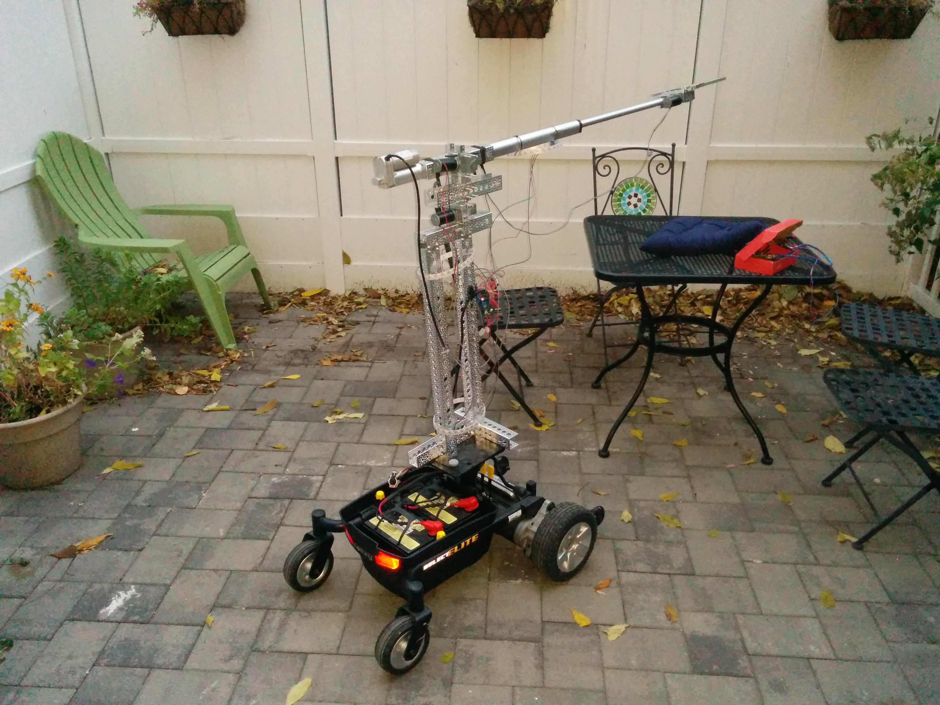
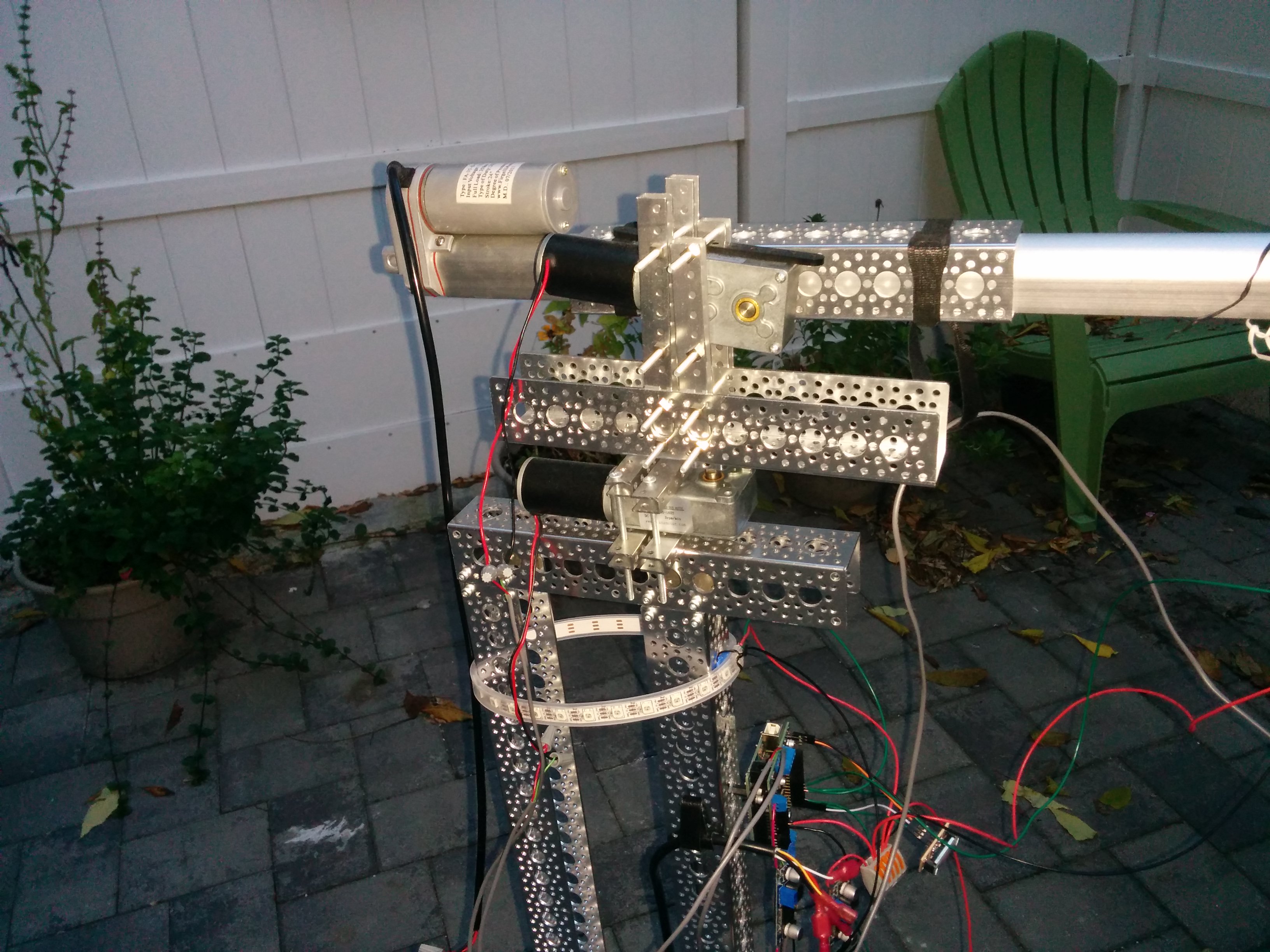
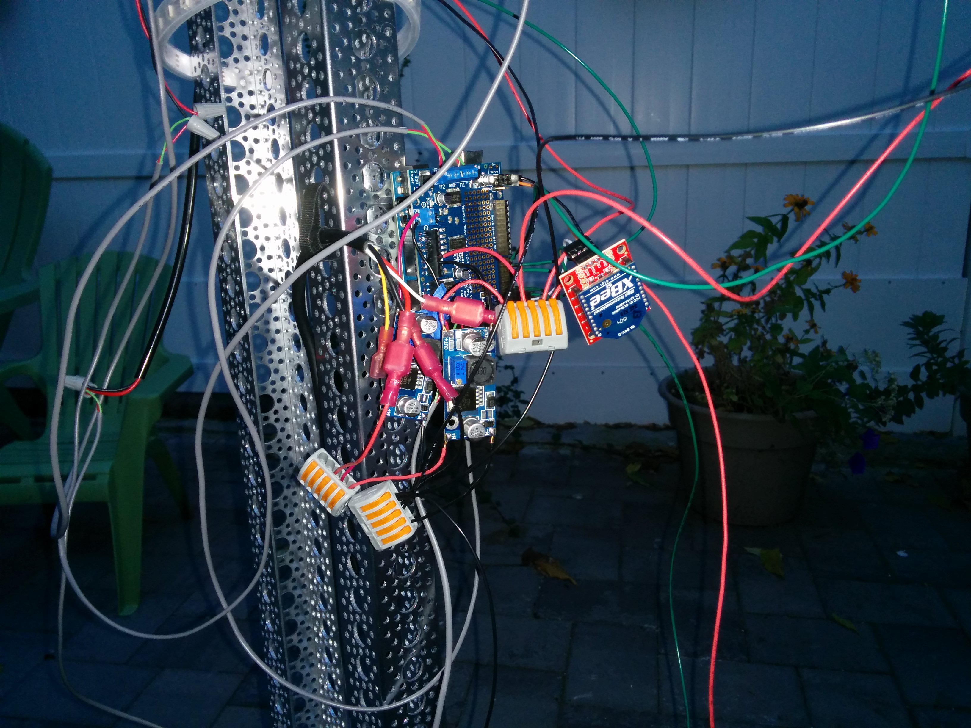
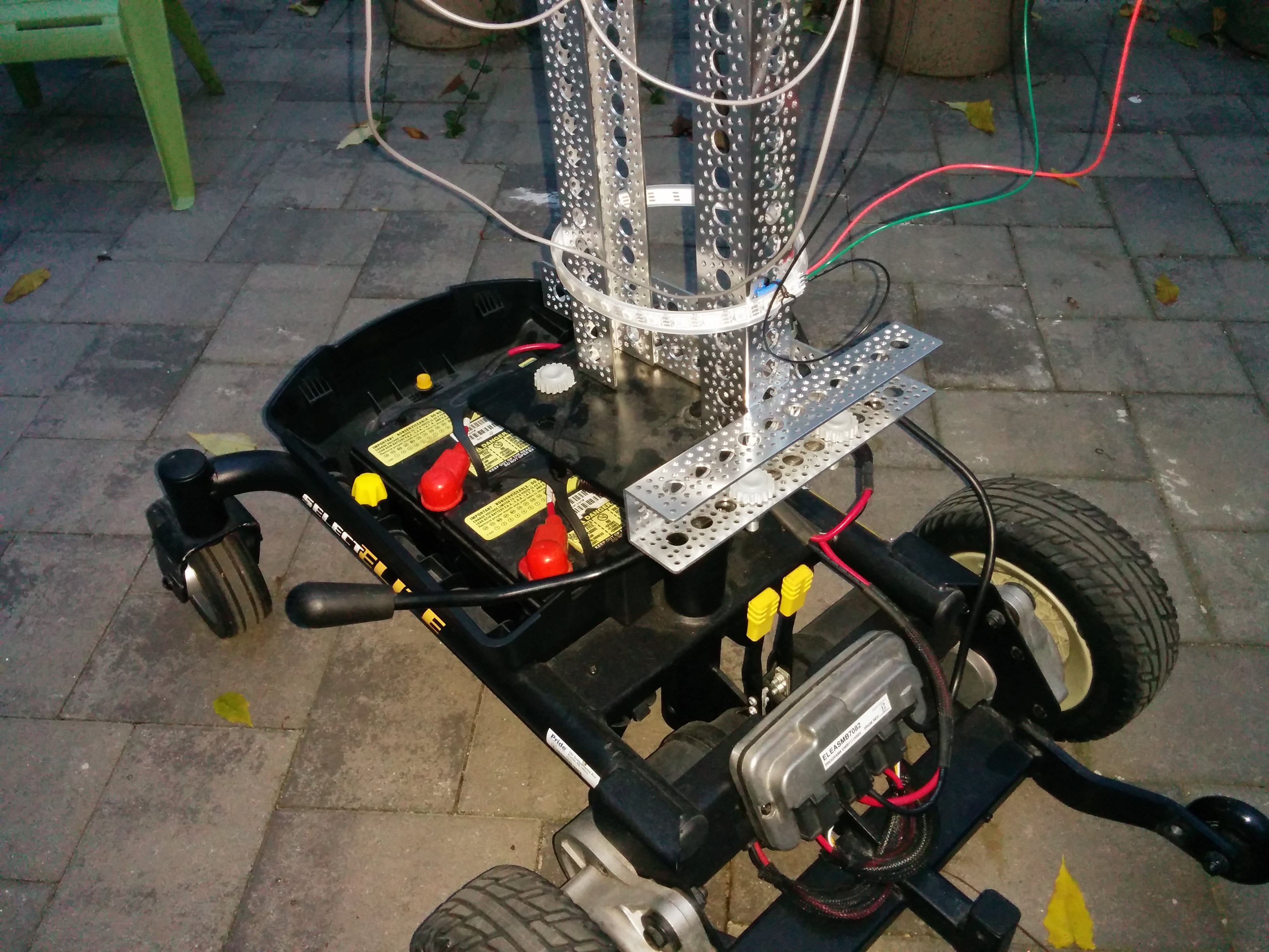
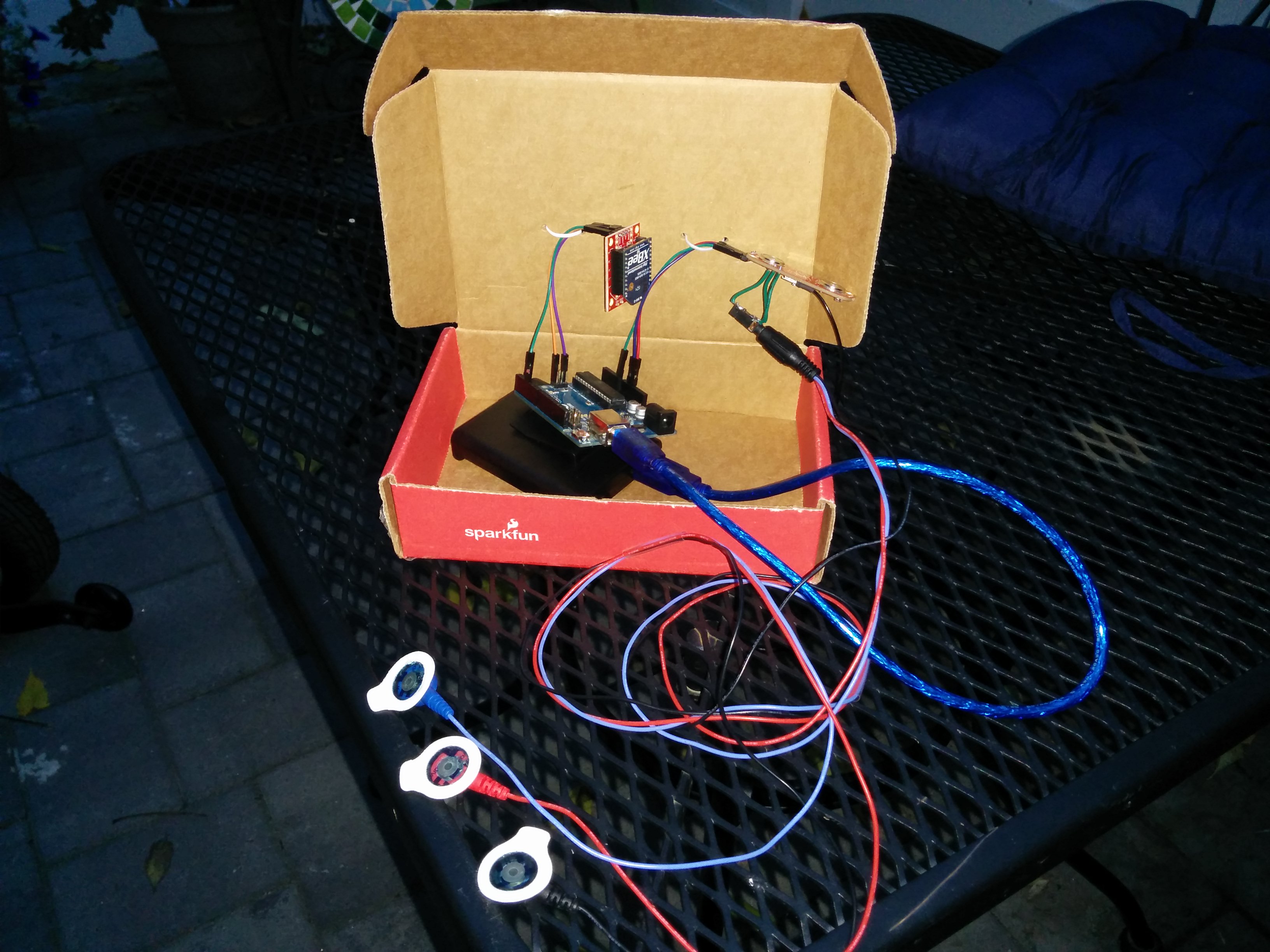
This setup uses an Arduino at each end to run the logic, each with an XBee for the wireless serial link. The robot end runs entirely off of its wheelchair base batteries, with DC buck converters to get the voltages I need. The EMG controller end runs off of a 4 AA battery pack.
For the EMG sensor I used this one:
http://www.advancertechnologies.com/p/shop_3.html
I wanted the flexibility of using a more traditional EMG electrode cable, so I soldered on an audio jack and plugged into that.
After wrapping up this demo, I also received this Arduino shield which I tested and works at least as well:
https://www.olimex.com/Products/Duino/Shields/SHIELD-EKG-EMG/
Here’s the code I wrote for this demo:
https://github.com/bobparadiso/EMG_robot
