
My past custom drive controls for PWCs were non-proportional, including the ones I produced based on eye-gaze, voice recognition, and winking. Non-proportional is the simplest to implement on a few levels, including the electrical interface to the chair itself. When connecting through the standard 9-pin connector, each direction (forward, reverse, left, right) is activated by simply pulling the corresponding pin to ground as detailed in my previous posts. A simple switch closure, relay, or transistor can achieve this.
I recently became very interested in the possibilities of custom proportional drive controls. So after some research and testing I got a very robust method working which could give full proportional joystick emulation including veering. I put this new method to work demonstrating single-switch scanning controls with veering.
Then I setup this voice based control with veering.
I’m very happy with how it turned out. It’s a much smoother and enjoyable driving experience than what non-proportional limits you to. Of course you can still turn in spot whenever you want just like non-proportional.
I’ve included the pin-out used by R-Net and Q-Logic here again for convenience.
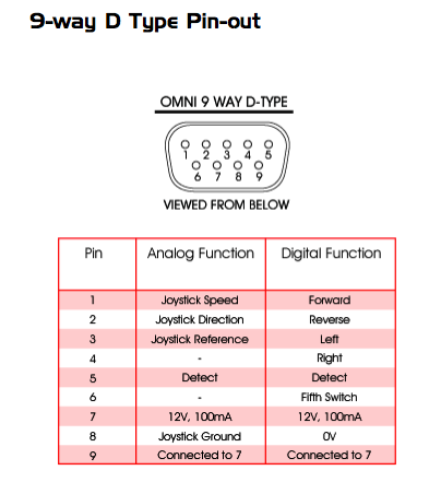
You can read more specifics in resources like the R-Net Omni Technical Manual, but to summarize the proportional pin-out and signals:
- 12V on Pin 7, GND on Pin 8
- You provide reference level on Pin 3, but it must be in the range of 49-51% of Pin 7
- Joystick Y-axis (speed) on Pin 1
- Joystick X-axis (dir) on Pin 2
- For both axis, +/- 30mV is neutral, full swing is 1.2V
NOTE: you must provide and maintain valid signal levels on pins 1, 2, and 3 within a very short time of receiving power otherwise the PWC will register a fault and you will be forced to power cycle.
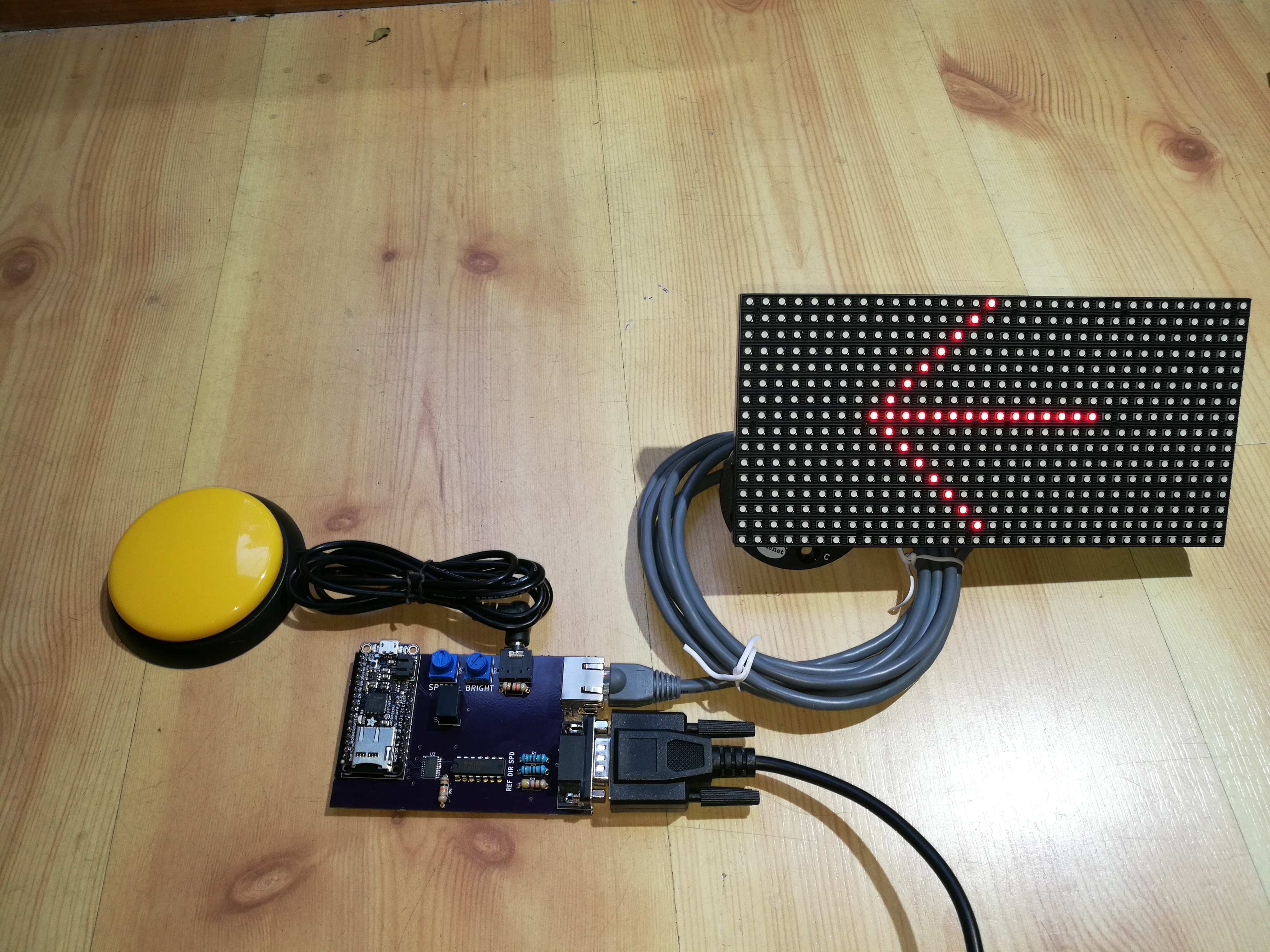
There are several ways to achieve the range of signal levels required, even within the boot time limitation. I chose to go with a digital pot, specifically the AD5263. I needed at least 2 channels (SPEED and DIR), but also wanted to use a 3rd channel on the same chip for REF to provide the best matching. SPEED and DIR need to each be within 30mV of REF for neutral. I also ideally wanted the simplicity of a pot that could work directly off the 12V rail. That way I wouldn’t have to amplify the outputs and again worry about precisely matching levels/amplification for neutral. Lastly I needed a setup that would as fast as possible output mid-scale on all 3 channels or else the chair would register a joystick hardware or calibration fault. The AD5263 has 4 channels, works up to 15V, and defaults to mid-scale on power-up. There are several other ways I found to achieve this including my first prototypes, but this way required the least parts and removed any dependence on having components matched with high precision. Here’s the board I ended up with, including pots to control speed and brightness of the display, connector for the display, 9-pin output to the R-Net Omni or Q-Logic Enhanced Display, and switch jack.
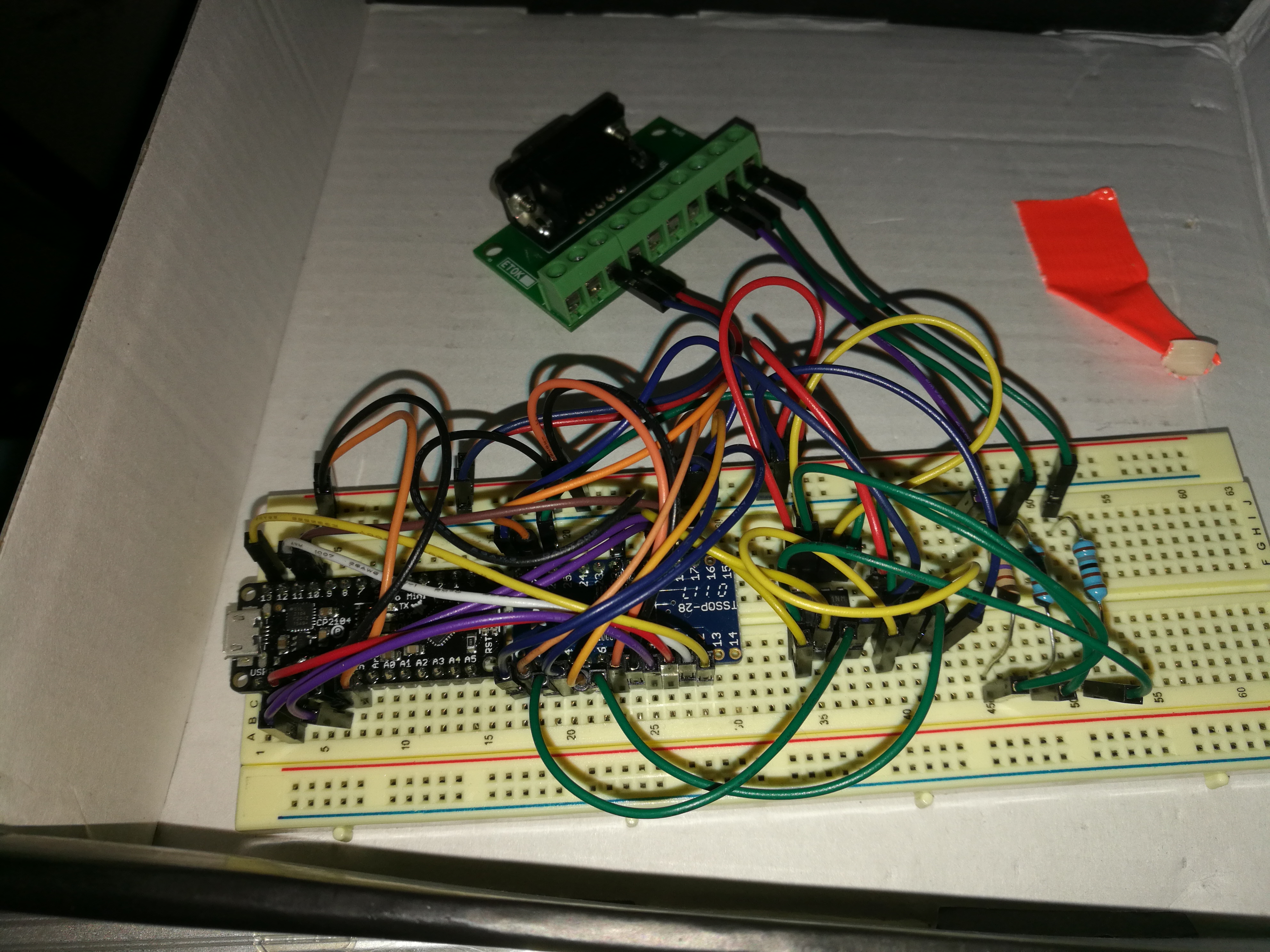
But it took some effort to get there. Here’s the first functional breadboarded prototype:
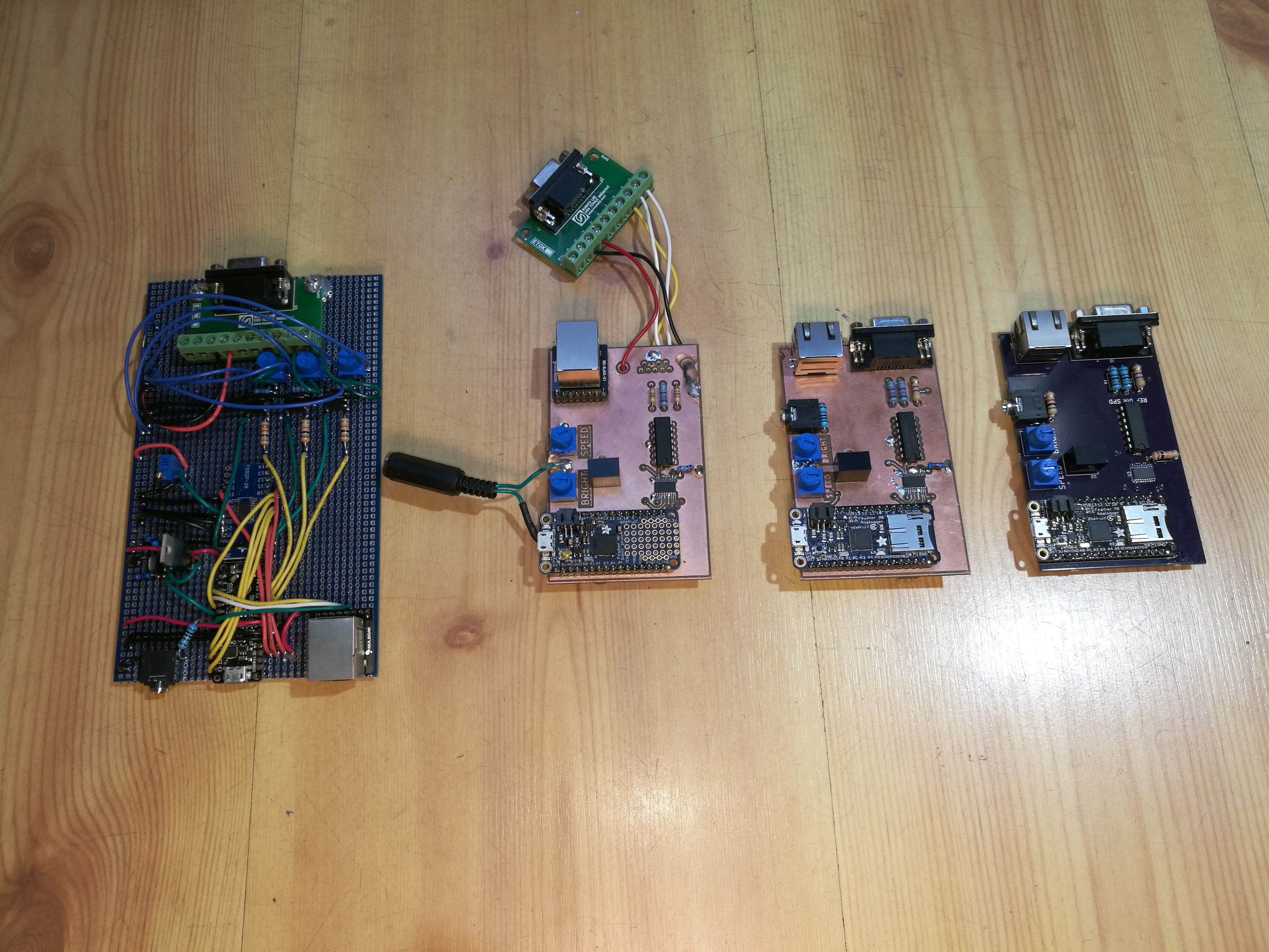
This process was accelerated with the PCB mill I recently purchased. I used OSH Park for the final boards, but for all the iterating in between the turn around time of using my own PCB mill was great.


For fun, here’s a sequence of board iterations starting from an early prototype before I had the PCB mill:
Schematic:

You can view the code I used for these initial tests at: https://github.com/bobparadiso/CustomSID

This is amazing and exactly the kind of single switch scanner I think would allow my daughter to drive a power chair. Is it possible to purchase one?
Hello. Thank you for your message. Please email us at bobparadiso@gmail.com so we can discuss some options. Thank you.
I’ve shared your page here for discussion
https://www.wheelchairdriver.com/board/viewtopic.php?f=2&t=11652
What value AD5263 is required? 20k, 50k, or 200kOhm?
What is the purpose of the op amp buffers?
I believe I went with the 20K version. It’s not that much current draw, and would have the snappiest response.
You need the buffers to actively drive the voltage otherwise the voltage will get pulled/shifted by the resistor network in the omni.
As per the manual in Ch. 6 Specifications:
Click to access pgdt_omni_manual_SK78813-03.pdf
“This is the joystick signal that determines the forward/reverse component of
wheelchair movement. The joystick has a 1.8KΩ resistor in series with the speed
output as shown below. All voltage levels apply to the actual joystick output, i.e.
no load values. The Omni has an input resistance of 100KΩ to 0V.”
Thank you for deciphering. I had no idea what the manual was trying to imply in that section. Makes complete sense now.