
I was given 2 reels of blue LEDs so I figured why not add some blue glowing effects under and around my workbench. Pulling this off with a microcontroller is really straightforward but I wanted to try something more interesting instead. I’d been trying to think of a good op-amp project and this fit the bill. This video shows the final glowing effect with the speed turned up and the op-amp generated waveforms.
The main way to dim LEDs is to use PWM, varying the duty cycle, to control what fraction of the time that the LED is getting power. At a high enough frequency, instead of flickering, the effect is perceived as dimming.
I had read about using a comparator to compare a fixed voltage to a sine wave to produce a fixed duty cycle square wave. I didn’t want a fixed duty cycle, but instead a time-varying one like a slow sine wave. This hinted to trying to use a comparator against 2 sine waves, one fast(the PWM frequency) and one very slow(the frequency of the dimming effect). This was a perfect op-amp project as I could use op-amps both for the sine wave generation and the comparator.
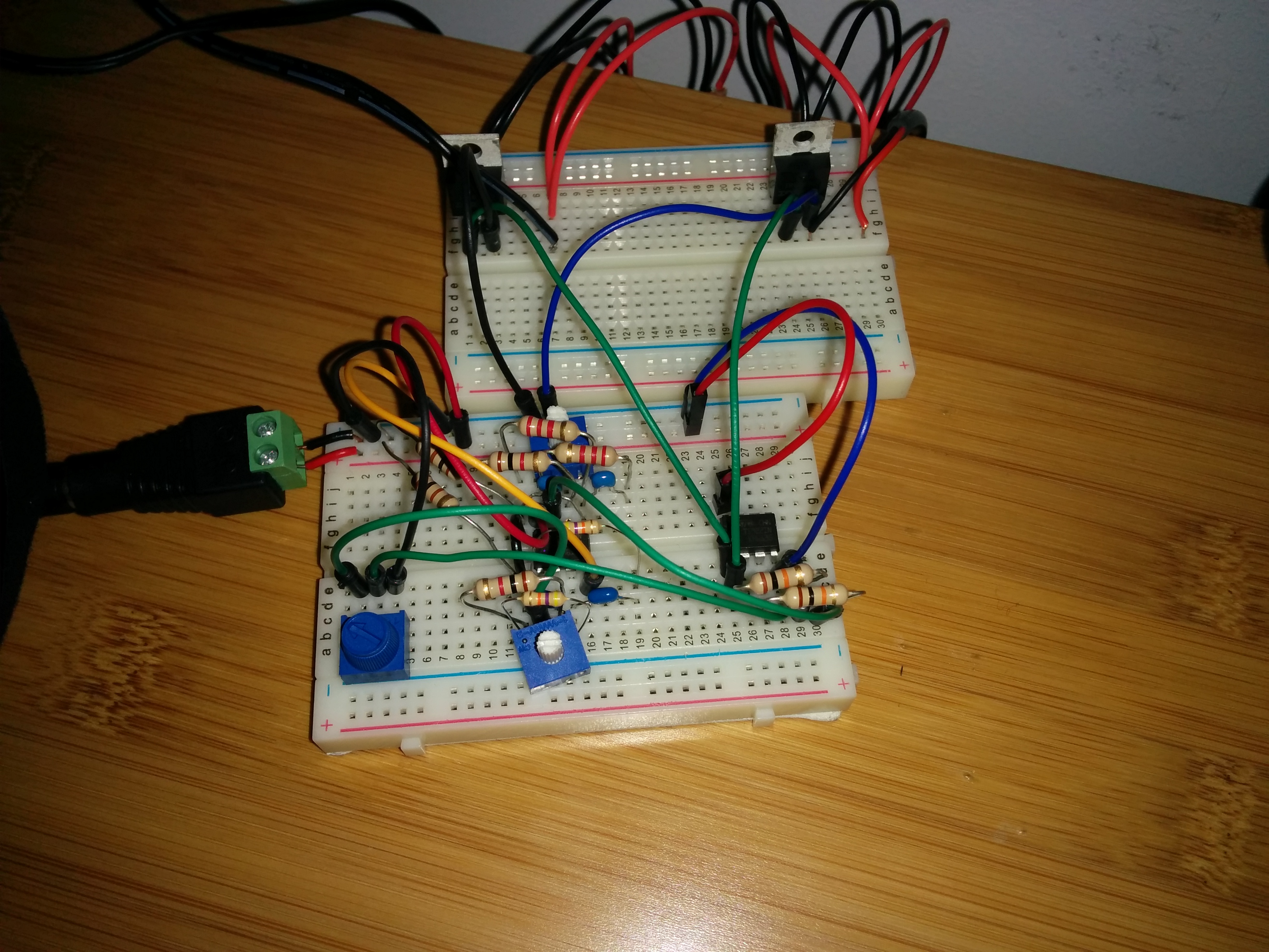
Below is the schematic of the circuit I created. I went with 2 basic Wien-bridge oscillators feeding into an op-amp as a comparator.

The frequency of oscillation is given by:
f = 1/(2*PI*RC)
The ‘slow’ oscillator is configured to give a fade up and back down duration of about 3 seconds.
1/(2*PI*47000*10*10^-6) = 0.33 Hz
The ‘fast’ oscillator is configured to give a PWM frequency of about 723 Hz.
1/(2*PI*2200*0.1*10^-6) = 723 Hz


Some references:
http://www.onegentleman.biz/Hardware%20Design/Op-Amp%20Oscillators/2013-Op-Amp%20Oscillators.php
