
I needed a powerful and stable wheeled base for a robot I wanted to build, so eventually I hit upon the idea of using the base of an electric wheelchair. I bought a cheap used one and learned that its motor driver actually has some significant logic and safeties which in hindsight makes a lot of sense. I could have bypassed all this and drove the motors directly but I wanted to see what headway I could make trying to communicate with that motor driver. Having made that choice, I also made the choice to not hack the wheelchair’s joystick, but to instead emulate the communication protocol it used. Here’s where I got:
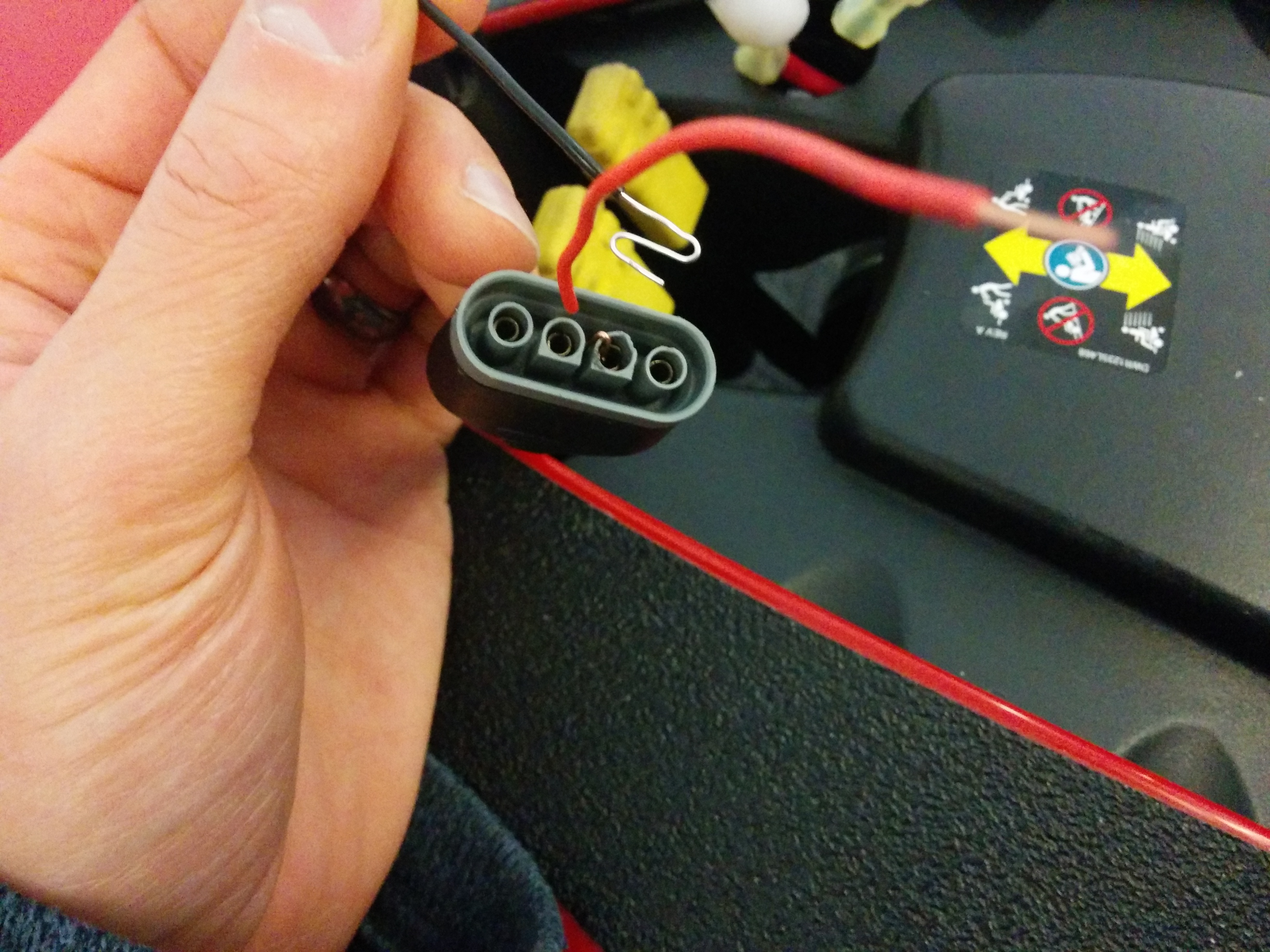
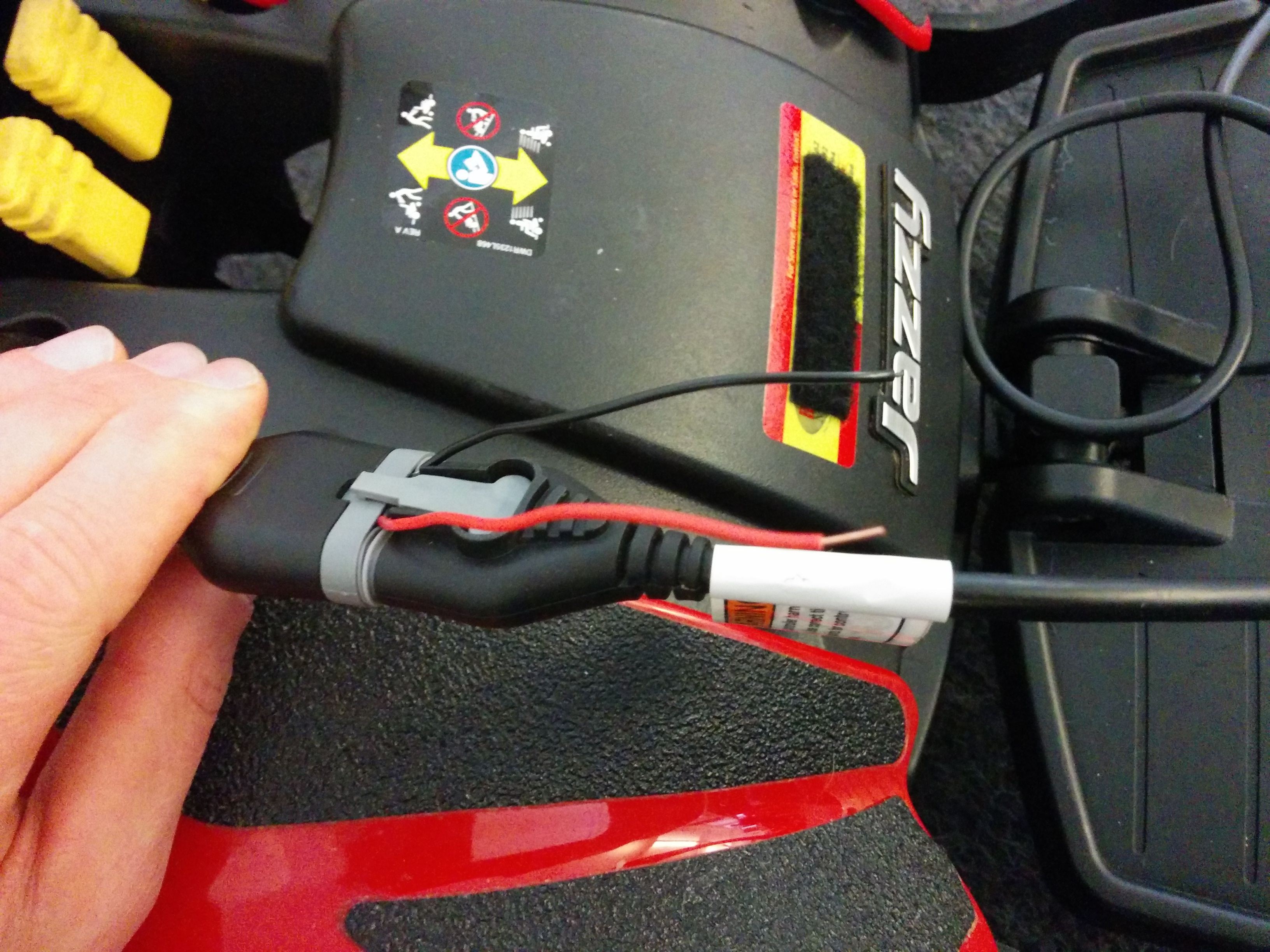
It took some effort, but it was a lot of fun figuring out the communication protocol that the joystick and the motor driver use. Firstly, there’s only one data line, bidirectional. running at 5V, and is actively driven both high and low by both the joystick and the driver, but of course not at the same time. The joystick always initiates a communication, and the driver always immediately gives a reply for just that message, then waits for the joystick to send again. If the joystick sends again too soon, even if still leaving room for the driver’s reply, it’s flagged as an error. Any error(including this one) will cause the driver to ignore all future commands from the joystick until you power cycle, or hold the data line low for a while as a reset before sending again. The joystick must set its data port to high impedance while it is not actively transmitting so that the driver can send replies on that same data line. There is a special ‘init’ message you must send first after a reset, then you can repeatedly send the standard message where you encode the status of the horn button, speed knob, and joystick x/y position.
The details of the message encoding are as follows. The bit width is 26 uS, ‘1’ is high. You send 6 packets: start, horn, speed, joystick-y, joystick-x, checksum. Each packet starts with “110”, then 8 data bits, finally an even parity bit. The 8 checksum data bits are calculated by adding together the other data bits of the previous 5 packets and then inverting the result. The horn packet has only one bit that flips: “10000100” vs “10000000”. The speed packet only the first 4 bits are used, rest are 0. The x and y are signed 8-bit values. During transmission, data bits are sent LSB first. Again, any error with the parity or checksum is flagged, and the driver locks out till reset.
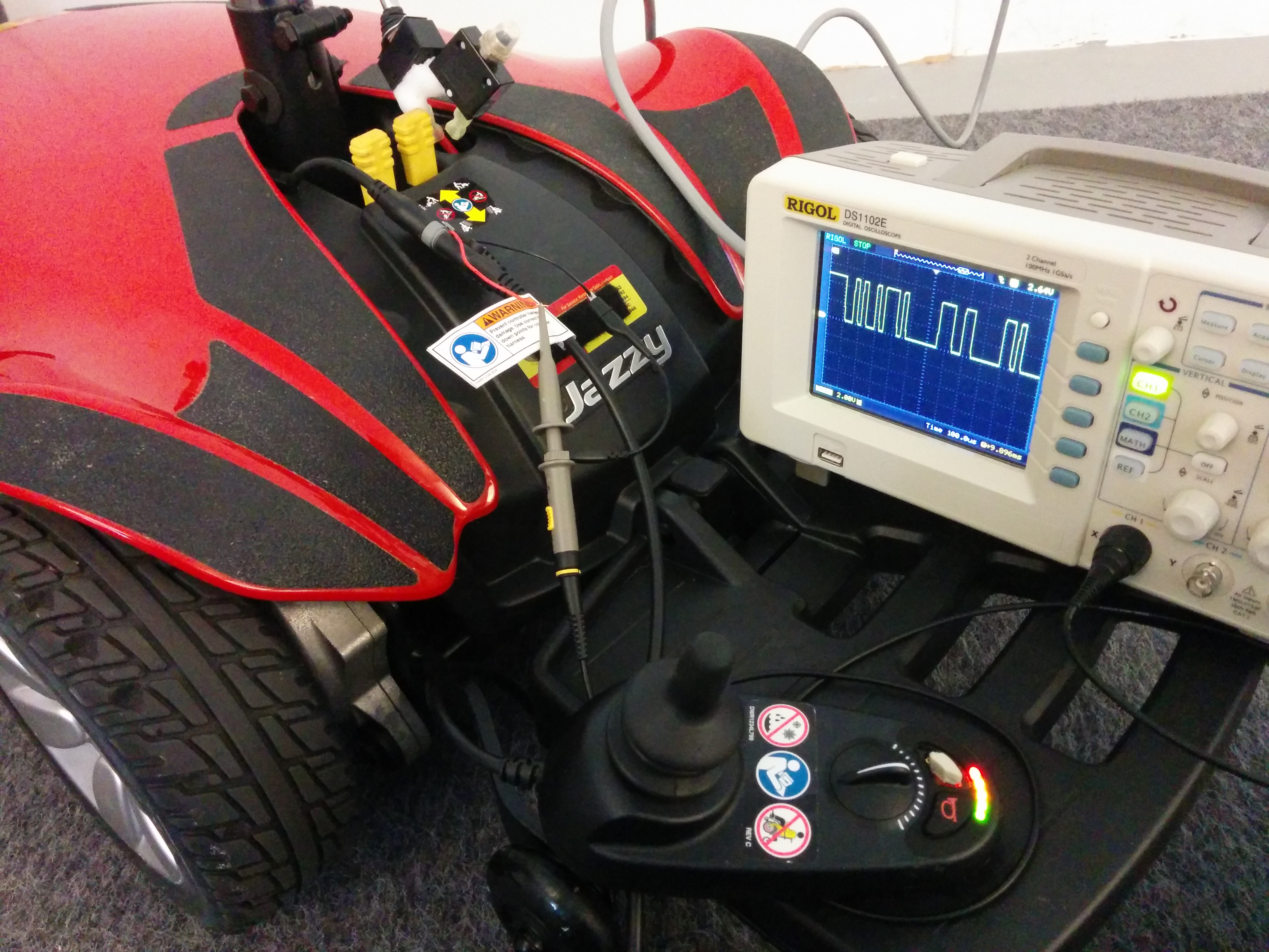
Here are some pictures of how I setup my oscilloscope to take initial measurements of voltages and timings. After having a general sense of what was going on, I switched to a logic analyzer and finally an Arduino to stream aligned bit patterns to a screen so I could begin deciphering the protocol as I moved the joystick.

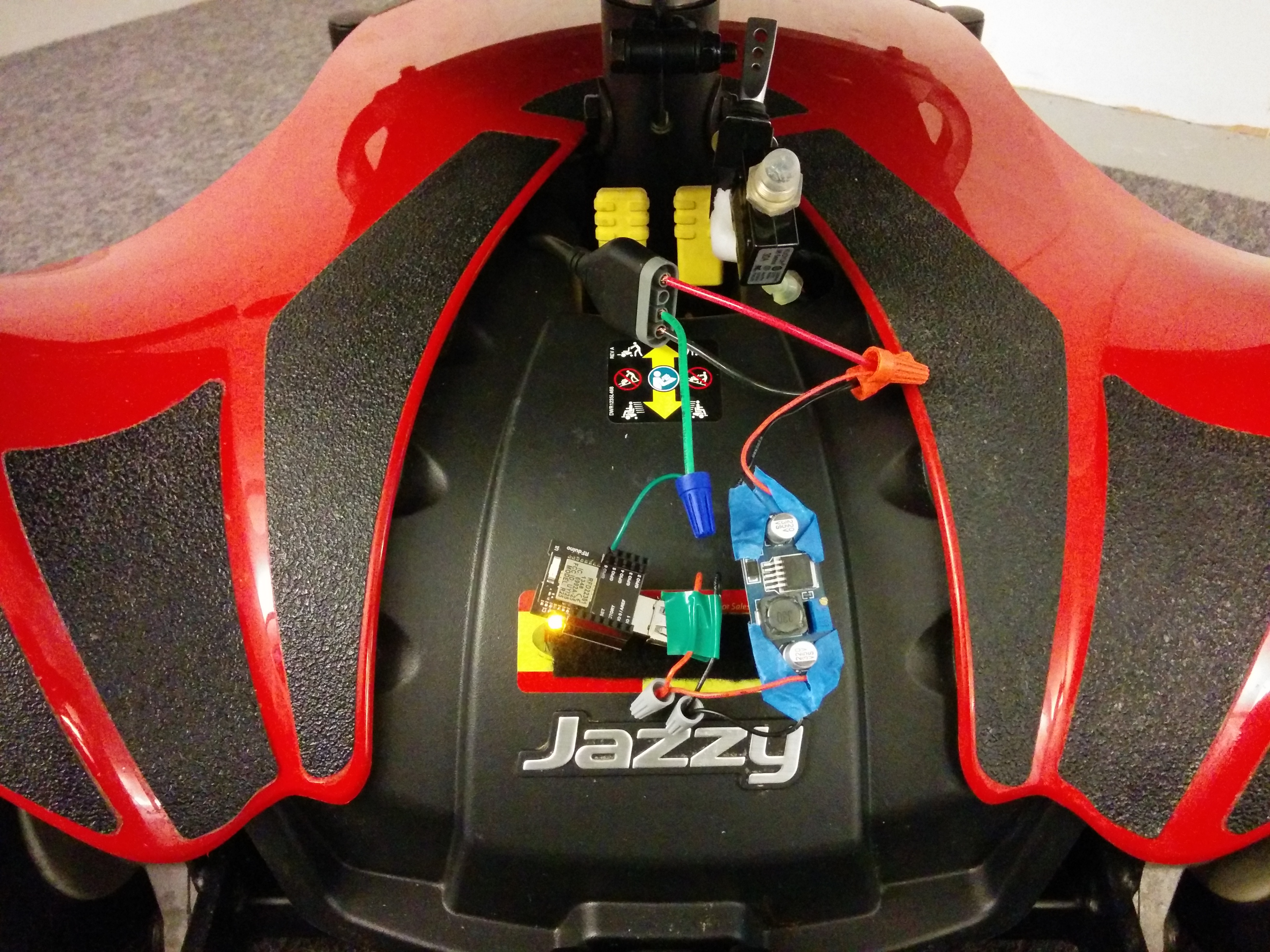
After I had things working with an Arduino Nano and an XBee controlling controlling the wheelchair remotely, I switched to my Android phone and an RFduino communicating over BLE. Upon getting control commands from my phone, the program on the RFduino sends the corresponding command codes to the wheelchair motor driver. I wired up a buck step-down converter to get the batteries’ 24V down to 5V, which the USB adapter then brings further down to 3.3V. I also wired up an extra kill switch, just in case.

Definitely a fun project and rewarding to decode a protocol and add RC capabilities to a large object. I’ve uploaded the code here: https://github.com/bobparadiso/BLE_wheelchair.

3 thoughts on “BLE Controlled Wheelchair”