
I recently came across a Wild Thing Modification by the Barstow School and FRC Team 1939. They did a really amazing job and the end result looks great and is very functional. Seeing what they had done I was inspired to get a Wild Thing, see how it worked and begin to explore what else I could push it to do including remote control and eye gaze control.
For the Barstow School project they opted to completely replace all the of the toy’s electronics including motor driver. There are some advantages to that approach including no need for reverse engineering and also having complete and direct control of motor drive parameters including the ramping up and down of speed. But still, I thought it would be informative to see how far one could get by keeping most of the toy’s electronics in place and just emulating the joystick sensors to control the Wild Thing. After getting this working it deserved a real test so I added remote control:
Having already worked out everything about the controls to get that working, it was trivial to switch adapt the toy as shown below. Speed, ramping, momentary vs latching, etc. can all be tweaked as desired.
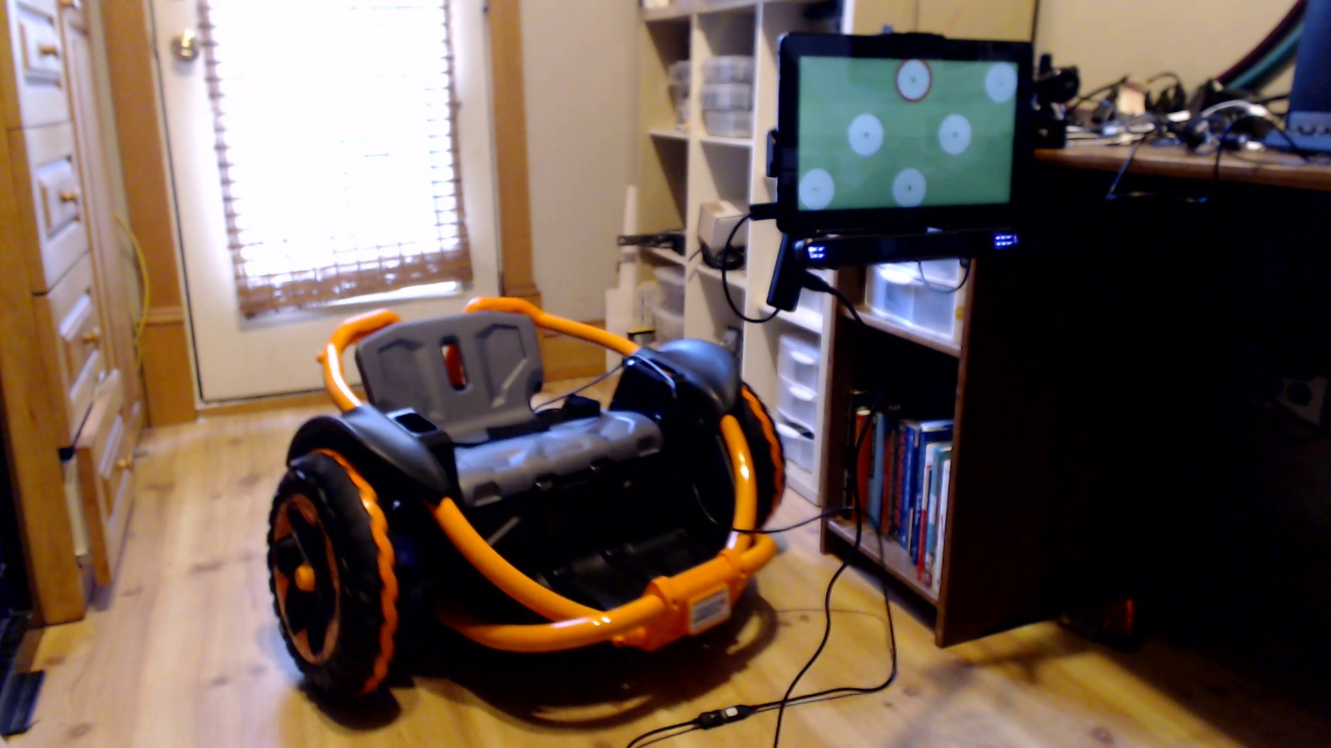
Lastly for this round of tests I hooked the Wild Thing up to eye gaze based driver controls I created. In the video below the eye gaze setup and myself as the driver are outside the vehicle, but of course the eye gaze could be mounted to the toy itself allowing the rider to drive using only their eyes.
Pictures of the unmodified Wild Thing including the control electronics under the seat in the battery compartment:


Looking at the wiring my first surprise was how many wires were on the joystick ports on the main board. I thought each joystick would be a pot, which would be 3 wires, but instead I saw 5. Taking apart the joysticks I saw that they used a combination of magnetic pins with sensors and a flex sensor for each joystick. These same magnetic pins with sensors were used in the seat switch, surprising me again as I would have thought they would have just used a mechanical button or microswitch.
Pictures of the joystick electronics:


Pictures of the seat sensor electronics:


After first working out GND, I probed the voltages on each of the other joystick wires as I moved the joystick through its full range. To do this and to set myself up to later inject signals I cut and stripped the wires and soldered on header pins.


Having worked out all the sensor output voltages it was easy to emulate the joysticks with 2 DAC outputs each and the seat sensor directly with a GPIO. DAC was the simplest way to go for the joystick wires since one of them was not high impedance and would sink 3 mA at the center voltage.
JOYSTICK:
- yellow = GND
- black = mag sensor
- green = flex sensor
- white = indirect 3.3 V
- red = 3.3 V
- CENTER: black = 1.49 V, green = 1.65 V
- FULL FORWARD: black = 2.68 V, green =3.03 V
- FULL BACK: black = 2.68 V, green = 0.01 V
- Anywhere In Between: black = 3.28 V, green = proportional value in between (eg. mid forward = 2.3 V)
- NOTE: for the second joystick the range is reversed.
SEAT SWITCH and SPEED SELECT BUTTON:
- black = GND
- red = Battery +, around 13 V
- white = Speed Sel button (high Z input: 3.3V released, 0V pressed)
- green = Seat Switch button (high Z input: 3.3V released, 0V pressed)
For sake of completeness, I’ll also document that the motor driver uses 30 kHz PWM and that the motors can pull a total upwards of 6 A under strain.
This toy definitely proved to be very hackable and versatile. Please note that these control modifications (remote control, switches, eye gaze) are not limited to this modification method. They could have just as easily been implemented on top of replacing the motor driver if desired.


Bob, I freaking love your work man! Do you have any familiarity with transparent eye-gaze controllers? If the screen were transparent it would prevent the rider from having to choose between steering and seeing where they are going. Really awesome work as always! Thanks for sharing!
Thanks man! I haven’t seen transparent eye-gaze controller package but 2 alternate methods I’m aware of include:
*showing the view from a forward facing cam as the screen background
*doing eye tracking without a screen, just the eye-tracker camera
I seen other projects using variations of those and some of my future work will explore those options as well. To your original idea, there are transparent screens by LG and others that may be more of an option as the price comes down and they’re more mainstream.
Thank you so much, Bob! One of our kids cannot engage both the weight switch and the motor controls at the same time. They have to lean forward using trunk force to move the joysticks which unweights the seat. We want to rewire the seat and speed control switch to use an on/off switch and a potentiometer for speed control but are having a hard time determining if this would be possible based on what input the wild thing controller is expecting.
Do you have any suggestions on wiring or possible solutions?
Hi Joe,
Thanks again for your comments. I can imagine a way to do what you are after but it is quite involved. Please email us at accessredefined@gmail.com if your budget allows for a professional consult and we can try to help you.
Best,
Bob
Wow- I’m a physical therapist and I freakin love engineers! Are you planning to distribute your schematics to somewhere like UCD Go Baby Go?
Thank you for your comment! Do you work with any families that need one? We are currently customizing and selling them. We would be happy to talk with GoBabyGo if they were interested but this is a level of electronics and customization far beyond what they currently perform. We configure these for eye gaze, voice control, EMG, etc.
Bob
what is your price for a switch enabled ride or a joystick enabled ride?
Hello Jim,
Thanks for your question and my apologies for a slow reply. I encourage people to contact us at accessredefined@gmail.com so we can gather the necessary information and provide an accurate quote, especially since there are many ways we can customize the end result to fit specific needs. But for either of those you mention, including our warranty and a remote control (so that the adult helping can override the controls providing an extra layer a safety and functionality) the ballpark is around $2K.
Bob
Can I ask where you got your added back seat or what it’s called? We purchased a wild thing for our son with SMA and he will need a bit more head and truck support and the blue seat in the photos looks perfect. Thanks for any advice/info!
Hi Ana,
That seat was a Firefly GoTo seat:
https://www.fireflyfriends.com/us/goto-seat
I’ve also seen Special Tomato seats work:
https://www.specialtomato.com/
-Bob
Bob, thank you for posting your progress. I am in the process of adapting a wild thing for a student at my school. Working on making child control mode and parent (remote) mode. Your ideas have really helped me organiz my thoughts on this! Great work.
Thank you for your comment Matthew! I hope all is well. If you run into any issues please do not hesitate to reach out.
Bob! I LOVE this! Do you have instructions on how to control the speed and hook up the switches with the pre-existing hardware? Are you able to get it slower than the preset speeds?
Have you tried an uprider from Rollplay?
Thank you Margaret for your comments. To hook up switches and control the speed you need to add some amount of custom hardware/electronics beyond the pre-existing hardware. Though you certainly don’t need to go as far as we did, including the remote control, etc. Using their motor controller you produce slower speeds by simulating smaller joystick deflections. If you replace their motor controller than you can directly achieve a very slow speed. I don’t have any experience with the uprider yet but it looks like fun.
Bob – love the article and the ingenuity. I bought one of these for my son – he can use both hands, so we don’t need to add a joystick or remote controls. He plays wheelchair basketball and wants to use it to go get balls from the yard – tough to wheel thru the grass.
I was wondering, though how we could eliminate the switch. It is very finicky – ours stops all the time and then starts again after you move around. I added a toggle switch for on/off and have forced the switch closed mechanically – it is better, but it still gets stuck. I don’t know what to do with the four wires to eliminate the seat sensor board. I would be OK with setting it on 5mph and leaving it there if that helps?
Hi Mark,
Thank you for your comments. The Wild Things I’ve seen seem to “go to sleep” after some minutes of sitting “idle” and only a “seat cycle” or power cycle wakes it up unfortunately. If it’s not the idle issue that’s getting you I wonder if it’s just a faulty switch. The manufacturer put some pretty thoughtful safeties into this product but for some specific uses these safeties get in the way.
Best,
Bob
Hi Bob,
This is a great tear down and tutorial. I am working on converting one of these into R/C controlled for a friend of mine. I planned on not using the electronics in the Wild Thing and driving the two motors off of an ESC. I have found most people use the Sabertooth 2×25 ESC for Power Wheels which has 25A continous capability. Based on your description above, it appears that the motors are pulling only 6 amps. Do you know on the Wild Thing if the motors are driven straight by the 12V battery through this ESC, would the current still only be 6A? If so, there is a Sabertooth 2×12 that is lower cost that seems like it should work.
Thanks for you help and input.
Craig
Hi Craig,
My apologies for a very delayed reply. It’s been a while since I looked at the electronics. I seem to remember that it never gives the motor 100%. If it did, and if the motor was under heavy strain or stall, I can imagine it drawing over the 6A I measured. But, through some combination of PWM less than 100% and designing user scenarios where the motor is never stalled, you can be reasonably sure to keep current draw in check.
Bob
Hi Bob,
Good job on the reverse engineering. Question: You called the white wire from the controller “indirect 3.3V”. What does that mean?
So the main controller board takes an analog voltage in the roughly gnd – 3.3V range and the magnetic switch enforces a dead zone in the middle. Do you think a PWM with a simple RC filter would do the job?
Hi Chip,
My apologies for the very delayed reply.
You may have already figured out what you need to. The white wire doesn’t source 3.3V, it wasn’t directly connected to the 3.3V rail. Too much time has passed for me to remember but it was either through a resistor, the MCU, or something else, and perhaps was only provided as a reference voltage.
From what I recall, the reason I used a DAC followed by an op-amp was that you have to drive the signal wires pretty hard. They are not high impedance. In other words, they will draw current and pull your voltage to a different value than what your RC filter would otherwise produce if nothing was pulling current from it. You could engineer around this, but for me a DAC (with an op-amp as buffer if the DAC doesn’t have enough drive capacity) seemed a more robust and more flexible solution.
Best,
Bob
Hi Bob,
I think that they may have done a revision since you did your work. The mag etic switch in the controller is completely gone. They just judge dead zone with voltage from flex sensor. I built a RC filter with 10K and 1uF and the input impedance was high enough not to affect it. It’s working and done if you want to see video:
Regards,
Chip
Hi Craig,
I started with Bob’s 6A and looked to reproduce that measurement using the native electronics. I’ve got a Hall Effect non-contact current sensor that can measure DC current. The 6A looks like a pretty good number for nominal loads but it can go significanly higher under heavier loads. The native controller has a motor stall LED so I thought I would try hanging on to a wheel and stalling it out. First, I was never able to get the LED to come on and I was never able to hang onto it hard enough to actually stall it. It’s geared down and has lots of torque. Second, I was able to get it to pull in excess of 20A even with the native controller.
I did some research on the native controller board and I think they did a good design. They have good low Rdson MOSFETs and a nice TI driver/protection IC. I don’t think you are going to get much more through a 3rd party controller except that your using a heavier gauge wire could lower total resistance in the circuit.
Regards,
Chip
Hello, Thank you for all the useful information.
I was able to implement an adapter controller to use the original board.
I followed your idea and used a micro-controller and a DAC to generate the required voltages for the black and green wires.
It all works well, but occasionally the motors spin the wrong way.
The code is simple and was debugged, so I am assuming an hardware bug.
Have you experienced any similar issues using a DAC?
Thank you
Cheers
Chris
Thanks for your message Chris. I haven’t had that issue but I’ve only used the earlier versions and I’ve gathered that the Wild Thing electronics have gone through several iterations. I’m pretty sure even at one point the voltage range was flipped for at least one side. Unfortunately I also think they were having a lot of various issues, especially in later versions as you can see in reviews here and other places: https://www.fisher-price.com/en-us/product/power-wheels-wild-thing-fgf77
I’m sorry I don’t have any specific information to share. My only advice would possibly be, if it happens regularly enough, to see if it still happens with the original joysticks. If not, maybe there is a specific voltage range that causes it to bug out (or to believe the older voltage range joystick is plugged in, maybe it autodetects based on initial voltage somehow). I’m not sure.
There’s always the nuclear options of trying another one, or replacing the motor driver itself. Sorry.
Bob dear Bob help a mother! I’ve got this thing all pulled apart I’m looking at the switchboard which I am the amateur at. How do I bypass the seat control? Our little magnet stick is wore out and there’s no replacement parts for sale at the moment. Do I solder a wire from the Green contact area to the c4? Where do I cut the wire completely out?
Hi Darcy,
I’m sorry. I don’t have any easy answer especially considering if you don’t have experience. Also keep in mind I haven’t looked at the Wild Thing in some years, and your version may be different than mine as the electronics went through a few different versions. It’s also important to note that the seat switch is a safety Fisher Price added, also as per their design, when the Wild Thing “goes to sleep” after being idle for some minutes, you can only “wake it up” by toggling the switch (kid gets up out of seat, then sits back down).
I’m not recommending it, but with the version I had (which may be different than your version), one could consider wiring a switch between the black wire (GND) and the green wire. Flipping the switch one way would simulate the kid sitting in the seat, the other way, them getting up out of it. But, if you have a different Wild Thing, or make a mistake, you could cause a short of the electronics which is dangerous.
I’m sorry I could not be more helpful. Good luck.
Best,
Bob