
These slot cars are another toy I adapted originally for Roosevelt Children’s Center. It would have been relatively simple to directly switch adapt one of the taps inside the slot car controller and this would have not involved any extra electronics. However that approach has a number of possible disadvantages. Firstly the user would need to maintain the switch activation for the entire duration of the desired car movement (unless using a more expensive switch with timed or latching electronics built-in). Secondly the switch activation would only produce one power/speed. This is often a problem since the power required to get a slot car moving or unstuck is usually higher than the maximum speed that the car can safely go around the entire track without flying off on the curves. The version I present here gets around these issues.
In my version, a microcontroller is used to vary the power applied to the cars to achieve several different effects. For the initial fraction of a second that a car begins trying to move, a high level of power is delivered to get the car going. Then the power is immediately stepped down to a level that produces the maximum safe speed for the car around curves. This is maintained for as long as the switch is activated. From that point the power is lowered over a configurable period of time so that the car decelerates. This can motivate the user to do another switch activation to speed the car up again. If not, after a period of deceleration the power is finally cut off and the car stops. This time period is configured to be long enough so that the car’s movement is still rewarding. From a stop, a new switch activation starts the car again with a surge of power. All of these timings and power levels can be configured to work well with different tracks and be rewarding and motivating to different users.
Here are pictures of one of the original controllers.


That type of controller would be extremely difficult or impossible for many children with disabilities to hold, let alone activate. Further as originally designed it requires constant pressure on the trigger to keep the car moving which can be another challenge. The second picture there shows the turns of high resistance wire that the wiper scrubs across to enable controlling the car’s speed.
Here are some pictures of the original power and controller connections to the track.


You can see 3 pairs of connectors (power in the center, controllers on either side). The metal strips shown here on the track underside connect power to the rails of the slots. The resistive wire in the controller was setting the amount of current to control the car’s speed.
Here’s a picture of the initial breadboarded prototype circuit with a microcontroller, one switch jack, one power jack, and a driver circuit for each car consisting of a MOSFET and flyback diode. Since the cars only go one direction around the track an H-bridge is not needed and this simple circuit does the trick.
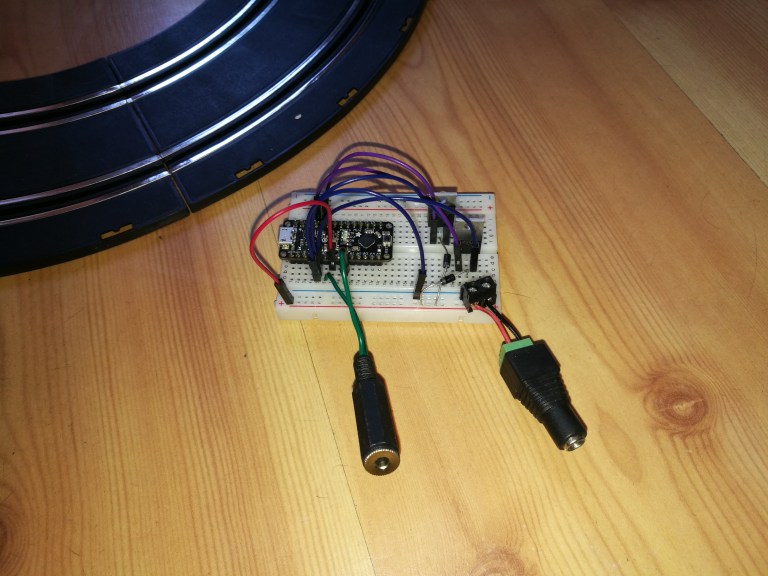
In this setup, the speed of the car is varied by varying the duty cycle of a PWM signal to the gate of the transistor.
After testing that proof of concept I produced this more robust soldered version in a plastic enclosure with 2 switch jacks and a jack for power.


I’m very excited about how well this came out. Everything is configurable in the firmware, and a single switch could even be set to control both cars at the same time.
You can grab the code I wrote here: https://github.com/bobparadiso/SwitchAdaptedSlotCars
