
Roosevelt Children’s Center was interested in having this claw crane toy switch adapted. I decided to give the toy 2 different modes. One for very young children who could benefit from and enjoy a simple cause and effect setup. The second mode allows complete control of the claw’s movement in all directions while still only requiring a single switch. Here is a video of this adaptation in action:
As you can see in the video, the first mode is a simple cause and effect setup that children love to watch. Upon hitting the switch (which could be any switch plugged into the switch jack I added) the crane dances around a bit then attempts to pick up a toy, and finally delivers it to the drop area.
In the second mode, the crane moves in each way it is capable of, one at a time, each for as long as the switch is pressed. First press does movement to the right, followed by left, backward, forward, down to grab, and back up. This continues to cycle such that the next press triggers movement to the right again, etc.
Below is a video of the toy being used by a 4 year old at Roosevelt Children’s Center. He is triggering the toy through our wireless IMU motion switch which allows him to enjoy and follow the crane game in action without worrying about targeting and motor planning to activate a switch.
The single switch claw crane controls are implemented with a microcontroller listening for switch presses. It then simulates the appropriate joystick activations by powering solid state relays that make the same connections that the joysticks would for each direction.
Here are some pictures of the initial teardown of the toy:


Here’s the mapping I worked out from buttons to existing solder connections I could use:


After working out where I wanted to tap into the existing circuit boards, I soldered on some wires that I could later connect to the new board I would create.
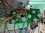


Next was to solder up the MCU and SSRs to control the other boards. The connecting wires between the boards were thin and also under potential strain as I moved the boards around so after I soldered each pair I added strain relief with hot glue. I also in the end added a jumper on the board to disconnect the power rails of the old and new boards so that I could optionally power only my board when updating the firmware over USB.


At this point I could test much of the functionality, but the last important feature missing was the switch jack. NOTE: As usual I placed a 1k ohm resistor in series with the input pin to help limit the current from transients and protect the pin. This can be important especially with switches that have very long wires. The other connection of the pair I connect straight to GND.


The last piece of the puzzle is the firmware running on the MCU, an ATmega328 on an Adafruit Pro Trinket I had laying around. Most of it is pretty standard in a way except for the idea of having to keep triggering the START button keep the toy active. Apparently there’s a timeout normally and the game ends until restarted by hitting the start button again. Since I did not desire the timeout functionality, I bypass it by triggering the start button in a repeating timer callback I have setup.
You can grab the code here: https://github.com/bobparadiso/SwitchAdaptedClawCrane

One thought on “Single Switch Claw Crane”